Harman Kardon AVR 445 Скачать руководство пользователя страница 20

When all audio, video and system connections have
been made, the final steps before listening to your new
AVR are to make the configuration adjustments that
tailor the unit to the other components in your system,
as well as accommodate your personal listening pref-
erences. A few minutes spent to correctly calibrate and
configure your system will greatly add to your listening
pleasure.

Speaker Selection and Placement

While the most seamless surround sound reproduction
comes from the use of speakers with identical or care-
fully matched driver elements at each position, no
matter which brand or type of speakers you prefer, it 
is always best to use the same model or series for 
the left front, center and right front speakers. Similarly,
it is also desirable to use the same model or series 
for the surround speakers. This ensures that the sound-
stage will be relatively seamless when a sound moves
from one side of the room to the other.

Speaker Placement

Once you have selected your speakers, it is important
that they be placed in positions that enable them to do
the best job of reproducing the sound as it was meant
to be heard, regardless of the program content. The
placement of speakers can have a noticeable impact
on the accuracy of the surround process, particularly in
multichannel systems.

When placing your speakers in a listening room, pic-
ture an imaginary circle starting at the center of your
video screen that arcs around the room with the prime
listening position, or “sweet spot,” at the center of the
circle. Depending on the number of speakers in your
system, there is a recommended placement along the
circle for each speaker, though the specific construc-
tion of your room, taking into account the available
walls, bookcases, or floor space at which the speakers
may be placed will obviously have some impact on
where the speakers are ultimately located. As a general
rule, try to place all speakers so that they are posi-
tioned at the same height as your ears when you are
seated at the prime listening position.

Use the following suggestions as a guide, and make
the changes needed to fit the speakers to your room.
Don’t be afraid to experiment a bit until you find the
right combination of locations that works for you. At
the end of the day, there is no real “right” or “wrong”
place to put the speakers; work to optimize their loca-
tions so that audio moves across the front of the room
smoothly, without seeming to jump from one speaker
to another.

Front Left/Right Speakers

The recommended placement for front left/right
speakers is at the 30-degree position with reference
to the center channel speaker. The distance between
them should be about the same as the distance from the
center channel speaker to the prime listening position.

Although the natural tendency is to place the speakers
so they are parallel to the wall behind them, and thus
in line with the video screen, the preferred placement
is to angle the speakers slightly (“toe in”) so that they
point at the prime listening position.

Center Channel Speaker

The ideal location for the center channel speaker is at
“0 degrees” in our circle, directly in front of the prime
listening position. Place the center channel speaker as
close to the top (or bottom) of the video screen as
possible so that when you position the front left/right
speakers the tweeters of all three front channel speak-
ers are within 24" of one another.

Surround Speakers for 5.1 Systems

In a 5.1 surround system, an additional pair of
left/right speakers is added. Although many believe
that these speakers should be placed at the rear of
the room, the preferred position for them is at the
sides of the room, with rear placement a second
option when room conditions prevent the use of side-
mounted surround speakers.

When side-wall placement is possible, place the
left/right surround speakers at a point that is 110
degrees along our circle from the center of the video
screen. This translates to placing them to the side and
slightly behind your preferred listening position. If pos-
sible, angle the speakers in slightly so that they are
pointing toward the listener’s ears.

5.1 Placement Diagram

If it is not possible to place the surround speakers at
the sides of the room, the alternate position is at the
back of the room, at a spot that is about 150 degrees
around our circle from the center of the video screen.
Another way to spot the optimal, alternate rear-wall
mounting position is to place the left surround speaker
on the back wall so that it points directly at the front
right speaker, and to have the right surround speaker
point directly at the front left speaker. If possible,

aim the surround speakers so that they point inward,
toward the listening area, rather than perpendicular 
to the walls.

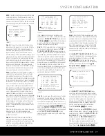
Surround Speakers for 6.1 Systems

A 6.1 surround system adds an additional speaker in
the center back surround position. We do not recom-
mend this configuration, as it will not deliver a full sur-
round sound field when any 7.1-channel mode is
used, since some signals will be sent to an output
(either left or right) where no speaker is present.

If a 6.1 system is to be used, first place the speakers
for a 5.1 system, and place the “sixth” speaker at the
center of the back of the room, pointing directly
toward the front center channel speaker.

6.1 Placement Diagram

Do not connect the center back surround speaker at
this time, as you must first run EzSet/EQ as shown on
page 26 so that the system configures the five main
channel speakers only. After completing the EzSet/EQ
process, connect the center surround back speaker to
one of the 

Surround Back Speaker Outputs

E

and manually configure the system for surround back
speakers, as shown on pages 29–30. DO NOT run
EzSet/EQ with only a single surround back speaker
connected, as a failure message will result.

We recommend that you consider adding a second
surround back speaker for a full 7.1 system, as soon
as possible.

Surround Speakers for 7.1 Systems

For the ultimate home theater experience, a 7.1 
surround system uses both traditional surround
left/right channels and a surround back left/right
speaker pair. In a 7.1 system, the front left/center/right
speakers remain in the same place as they would be
for a 5.1 or 6.1 system, but due to the number of
speakers involved, the placement of the surround
speakers is different.

In a 7.1 system, you should place the main surround
left/right speakers at the 90-degree point on our cir-

Center Speaker

Video Screen

Front Right

Speaker

Front Left 

Speaker

Side Surround

Left Speaker

Side Surround

Right Speaker

Back Surround

Speaker

Listening Position

110°

110°

30°

30°

Center Speaker

Video Screen

Front Right 

Speaker

Front Left 

Speaker

Side Surround

Left Speaker

Alternate placement

for Side Surround

Left Speaker

Side Surround

Right Speaker

Alternate placement

for Side Surround

Right Speaker

110°

150°

110°

150°

30°

30°

20

SYSTEM CONFIGURATION

SYSTEM CONFIGURATION

AVR445 OM  6/23/06  3:13 PM  Page 20

Содержание AVR 445

Страница 1: ...AVR 445 AVR 445 AUDIO VIDEO RECEIVER OWNER S MANUAL Designed to Entertain...

Страница 2: ...System Configuration 20 Speaker Placement 22 In Out Setup 24 Audio Setup 24 Surround Setup 26 Using EzSet EQ 28 Manual Setup 29 Speaker Size and Crossover 30 Delay Settings 31 Output Level Adjustment...

Страница 3: ...ile the main home theater uses a differ ent source Using the assignable rear surround chan nel amplifiers you may create a basic remote listening zone without any additional equipment or the unit s mu...

Страница 4: ...ght of the AVR 445 and the heat generated by the amplifiers there is the remote possibility that the rubber padding on the bottom of the unit s feet may leave marks on certain wood or veneer materials...

Страница 5: ...room mode 2 Surround Mode Group Selector Press this but ton to select the top level group of surround modes Each press of the button will select one of the sur round mode categories Once the button is...

Страница 6: ...r may be accessed gently pull the door down and toward you using either upper corner of the door Volume Control Turn this knob clockwise to increase the volume counterclockwise to decrease the volume...

Страница 7: ...tion on configuring the speaker settings see page 29 E Channel Adjust Selector Press the button to begin the process of manually adjusting the channel level outputs using the source currently playing...

Страница 8: ...ital Audio Output Z DVD Audio Inputs a Coaxial Digital Audio Inputs b Optical Digital Audio Inputs c 8 Channel Direct Inputs d Video 1 Audio Inputs e Video 2 Audio Inputs f Video 3 Audio Inputs g Vide...

Страница 9: ...ipped carrier Connect this jack to the IR IN jack on compatible Harman Kardon equipment D Center Channel Speaker Outputs Connect these outputs to the matching and terminals on your center channel spea...

Страница 10: ...o Output Connect this jack to the coaxial digital input of a CD R RW MiniDisc or other compatible digital recorder Z DVD Audio Inputs Connect the left right analog outputs of a DVD player or other aud...

Страница 11: ...de Button U OSD Button V Tone Control Button W Dim Button X Tuner FM Select Button Y Channel Up Down Selector Z Delay Select Button a Speaker Select Button b Memory Button c Numeric Keys d Stereo Mode...

Страница 12: ...ic 7 options 8 Direct Button Press this button when the tuner is in use to start the sequence for direct entry of a station s frequency After pressing the button simply press the proper Numeric Keys c...

Страница 13: ...on on the multiroom system R Macro Buttons Press these buttons to store or recall a Macro which is a preprogrammed sequence of commands stored in the remote See page 49 for more information on macros...

Страница 14: ...Line and both the DSP and Surround Off Surround Mode Indicators are lit you will enjoy a two channel presentation of the sound along with the benefits of bass management Depending on whether your sys...

Страница 15: ...the AVR 445 s Multiroom IR Input Jack N When it is used in the same room as the AVR 445 it will control the functions of the AVR 445 or any compatible Harman Kardon products in that room When it is u...

Страница 16: ...reen display press the Numeric Keys for the preset number between 01 and 30 that you wish to assign to the station or channel See page 39 for more information Tuning Mode Button When listening to AM o...

Страница 17: ...inal of each speaker connection has a specific color code as noted on page 8 However most speakers still use a red terminal for the positive connection Connect the negative or black wire to the same t...

Страница 18: ...signal in an HDMI connection Therefore the following connections are required when the AVR 445 is used with HDMI sources Connect the HDMI output of a source to either of the HDMI Inputs L Connect the...

Страница 19: ...a wide variety of compati ble optional devices that respond to voltage actuation commands This includes external audio power amplifiers video screens motorized blinds and other compatible products in...

Страница 20: ...el speak ers are within 24 of one another Surround Speakers for 5 1 Systems In a 5 1 surround system an additional pair of left right speakers is added Although many believe that these speakers should...

Страница 21: ...cessor Although it is necessary to assign input output settings and surround mode choices manually we recommend that you take advantage of the power and precision of EzSet EQ to automatically select a...

Страница 22: ...requirements However once done they need not be changed again unless your system components have changed When using the full OSD system to make the setup adjustments press the OSD Button U once so th...

Страница 23: ...he following ways depending on the input source Analog signals composite S video or component will output only in the resolution and format that matches the input for both the main Monitor con nection...

Страница 24: ...n UNLOCK message in the AUDIO IN line indicates that a digital input has been selected for that source but that no data stream is present When the input selection has been made press the Navigation Bu...

Страница 25: ...o modes The PCM 96kHz CONFIG group contains the surround modes available when a PCM digital data stream is present This includes not only 96kHz PCM sources from DVD or CD players but also all two chan...

Страница 26: ...now ready to start the EzSet EQ process by following these steps Step 1 Navigate to the EZSET EQ MAIN menu Fig 8 by first pressing the OSD Button U on the remote Press the Navigation Button n until th...

Страница 27: ...eaker is present Should this message appear make note of the suspect speaker location exit the menus and turn the receiver off Check all speaker wire con nections and then rerun EzSet EQ Figure 12 Ste...

Страница 28: ...t so that a baseline setting is estab lished and then make your adjustments from there Note that once EzSet EQ has been run you do not need to adjust all system settings only those that you want to ch...

Страница 29: ...r the settings that were established when EzSet EQ was run or the factory default settings if you have not yet run the automated system Figure 18 To change the setting for any of the four speaker posi...

Страница 30: ...is present and Large speakers are configured for the front left right position select NONE This will route all low frequency information to the front left right speakers When the SPEAKER SIZE menu ret...

Страница 31: ...elay Select Button Z The A V Sync Delay setting is first and it may be adjusted by pressing the Set Button p within five seconds of when the A V SYNC DELAY message appears in the on screen display and...

Страница 32: ...n adjustments but to have more control over the way the test tone is moved among the channels To circulate the tone manually first make certain that the CHANNEL ADJUST menu is on the screen following...

Страница 33: ...nu and then pressing the Set Button p so that you may make any other adjust ments to the system parameters If the changes just made complete the manual adjustments needed press the OSD Button U to exi...

Страница 34: ...our weeks Source Selection To select an input source from the front panel press the Input Source Selector Button 6 Each press of the button will move the input selection through the list of available...

Страница 35: ...pictures or TV pro grams bearing the logo of one of the major surround encoding processes such as Dolby Surround or DTS Stereo may be played in either the Dolby Digital Dolby Pro Logic II Cinema DTS...

Страница 36: ...ods of encoding the sig nals and thus they require different decoding circuits to convert the digital signals back to analog DTS encoded soundtracks are available on select DVD and LD discs as well as...

Страница 37: ...player is sending the correct signal to the AVR NOTE When an HDMI equipped video display is in use regardless of the type of source and whether or not it is connected through the AVR 445 it communi ca...

Страница 38: ...s The letters used by the Speaker Channel Input Indicators will flash to indicate when a bitstream has been interrupted This will happen when a digital input source is selected before the playback sta...

Страница 39: ...Button X by pressing the button up towards the top of the remote The first press of the button selects the frequency band and station or XM channel that was last tuned Press the button again to select...

Страница 40: ...ress the Memory Button b and note that a dash will start to flash next to the preset memory bank letter Within five seconds press the Numeric Button c from 1 to 8 for the memory slot you wish to use T...

Страница 41: ...ress the EzSet EQ On Off button A Using this feature does not change the settings it merely puts them in or out of the signal path Dim Function Since the AVR 445 will often be used when movies or othe...

Страница 42: ...r adjustments to make press the OSD Button U to exit the menu system Turn On Volume Level As is the case with most audio video receivers when the AVR 445 is turned on it will always return to the volu...

Страница 43: ...other options in this menu this is a per manent setting change and the Time Out entry will remain in effect until it is changed even if the unit is turned off If you wish to make other adjustments pr...

Страница 44: ...e MULTI ROOM menu First press the OSD Button U to call up the MAIN MENU Figure 1 Next press the Navigation Buttons D so that the cursor is next to MULTI ROOM then press the Set Button F When the MULTI...

Страница 45: ...he tuner is selected as the source for the remote zone any change to the frequency or preset will also change the station being listened to in the main room if the tuner is in use there Similarly if s...

Страница 46: ...the remote If desired or if the codes for your brand are not part of the remote s library at all you may still use the remote to program most infrared controlled products by learning the commands fro...

Страница 47: ...is means that the codes for the product you are trying to program are not in the AVR remote library and you will have to learn them into the remote following the instructions shown in the next section...

Страница 48: ...til the LCD changes again If the code was successfully learned you will see the display shown in Figure 40 In that case go to Step 10 If the LEARN FAILED display Figure 41 appears again you may either...

Страница 49: ...gure 47 5 Once the new device is selected the remainder of the process will select the codes for the specific brand to be used and for that reason they are identical to the way a device is programmed...

Страница 50: ...macro has been pressed continue to press the buttons you wish to be part of the macro in the order they will be used Press each button within five seconds of the last button remembering to press the...

Страница 51: ...NOTE FOR VOLUME PUNCH THROUGH The remote s default settings are for the AVR 445 s vol ume controls to be used when any input or device is selected with the exception of the VID 2 TV button There is n...

Страница 52: ...e returned to the factory default setting follow the steps shown above except that in Steps 4 and 5 select the same device for both the DEVICE IN USE on the left side of the bottom line and the PUNCH...

Страница 53: ...ss changes it to an H Consult the table at the end of this section to see which characters pressing a partic ular button generates 7 After you enter the first letter of the new device name there are t...

Страница 54: ...k to the next position Then press the Numeric Key c as required to enter the desired letter This is the way you would enter the second O in the word ZOOM and again for the letter M c To enter a blank...

Страница 55: ...mory Backlight Options The AVR 445 s remote has a built in backlight system that makes it easier to use the remote when the room lighting is dimmed for an optimal home theater experi ence To turn the...

Страница 56: ...ion you may find that they need to be changed sooner after the remote is programmed for the first time When the batteries approach a level below which the remote will not function the remote s LCD scr...

Страница 57: ...udio feed paused Resume play for DVD display and digital audio stops Check that Digital Input is selected Fan does not appear to operate Additional cooling may not be required The fan is activated onl...

Страница 58: ...ligibility and more accurate placement of sounds with fades and pans The Logic 7 M or Music mode enhances the listening experience by presenting a wider front soundstage and greater rear ambience Both...

Страница 59: ...dge ANALOG AUTO OFF ANALOG 6 8 CH Direct ANALOG AUTO OFF ANALOG USB AUTO OFF DSP DOWNMIX System Default and Personal Settings Worksheets The worksheets in this section show the system defaults for the...

Страница 60: ...s Feature System Default Your System Settings Front L R Speaker Size X Over Small 100Hz Center Speaker Size X Over Small 100Hz Surround L R Speaker Size X Over Small 100Hz Surround Back Speaker Size X...

Страница 61: ...r The Bridge USB 6 8 Ch Direct Input Title Surround Mode Audio In Port Audio Auto Poll Video In Port Component Video Input Video Processing A V Sync Delay Record Output Auto Poll ADC Sampling Tone In...

Страница 62: ...0 8 Selectivity 10kHz 30dB Video Section Television Format NTSC Input Level Impedance 1V p p 75 ohms Output Level Impedance 1V p p 75 ohms Video Frequency Response Composite and S Video 10Hz 8MHz 3dB...

Страница 63: ......

Страница 64: ...250 Crossways Park Drive Woodbury New York 11797 www harmankardon com 2006 Harman International Industries Incorporated All rights reserved Part No ZKD3101HA00...

Отзывы: