89
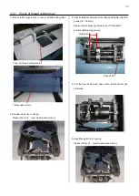
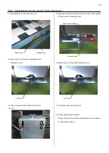
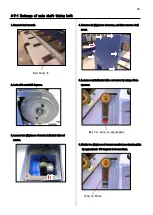
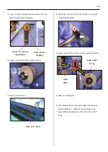
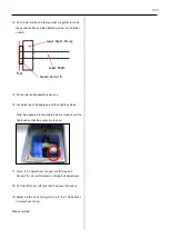
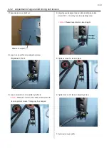
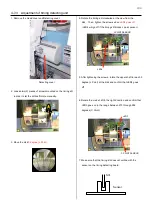
4-5-8 Adjustment of position of keeper
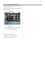
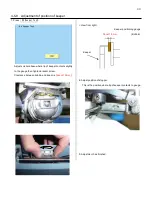
7. Press
#4 Keeper Test
.
Adjust solenoid base where tip of keeper contacts slightly
to the gauge then tighten bracket screw.
Clearance between bobbin and keepr is [
about 1.0mm
].
< View from right>
Keeper positioning gauge
About 1.0mm
(Bobbin)
Keeper
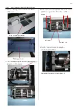
8. Adjust position of stopper.
This is the position where tip of keeper contacts to gauge.
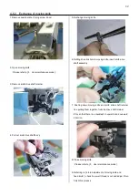
9. Adjustment has finished.
Содержание HCR3-1502
Страница 1: ... Maintenance Manual for Embroidery Machine HCR3E SERIES Version 1 2 HappyJapan Inc ...
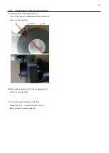
Страница 104: ...105 4 7 3 Adjustment of timing detecting unit 8 Finally put the cover back on ...
Страница 107: ...107 ...
Страница 172: ...172 E7 Electric system diagram E7 1 Pulse motor driver PMD wiring ...
Страница 173: ...173 E7 2 Pulse motor driver PMD setup ...
Страница 174: ...174 E7 3 Inverter wiring ...
Страница 175: ...175 E7 4 Electrical connection diagram ...
Страница 176: ...176 ...
Страница 177: ...177 ...
Страница 178: ...178 E7 5 List of electrical connection diagram ...
Страница 179: ...179 ...
Страница 180: ...180 E7 6 Explanation of function clrcuit board HCD8122 LCD CE MX Board Ass y ...
Страница 181: ...181 HCD8116 TP SW Circuit Board Ass y CN No Function CN1 Switch output LED input ...
Страница 182: ...182 HCR8121 CONT R2 Circuit Board Ass y ...
Страница 216: ...2018 9 HappyJapan Inc 9 5 TAITO 2 CHOME TAITO KU TOKYO JAPAN TEL 81 3 3834 0711 FAX 81 3 3835 8917 ...

