8
1
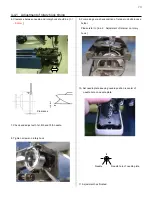
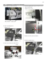
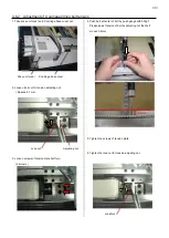
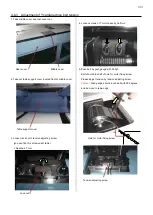
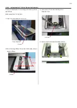
4-5-2 Adjustment of thread cutting driver
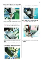
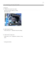
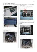
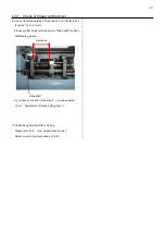
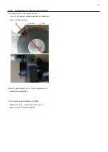
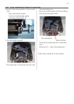
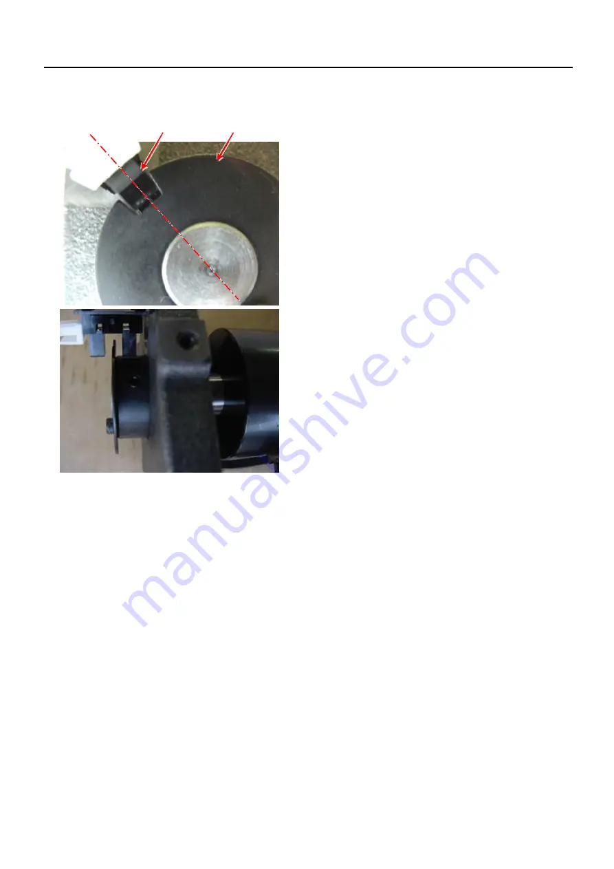
5. Adjust Slit right position against sensor.
If you off the position, please adjust sensor position by
screw on sensor bracket.
Sensor Slit
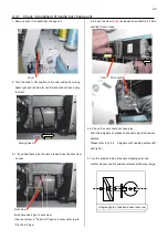
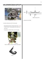
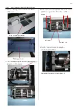
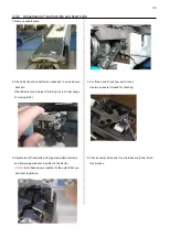
6. After it, please adjust [ 4-5-5 Check / Adjustment of
position of moving knife ].
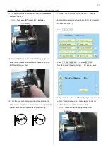
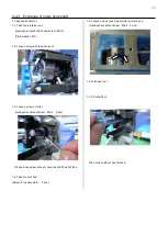
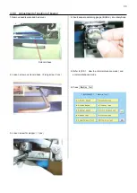
7. Confirm Moving knife position to CLOSE.
Please refer to [ 5 User maintenance mode ].
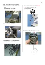
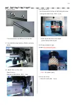
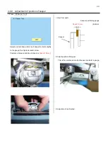
Back on covers to previous position.
Содержание HCR3-1502
Страница 1: ... Maintenance Manual for Embroidery Machine HCR3E SERIES Version 1 2 HappyJapan Inc ...
Страница 104: ...105 4 7 3 Adjustment of timing detecting unit 8 Finally put the cover back on ...
Страница 107: ...107 ...
Страница 172: ...172 E7 Electric system diagram E7 1 Pulse motor driver PMD wiring ...
Страница 173: ...173 E7 2 Pulse motor driver PMD setup ...
Страница 174: ...174 E7 3 Inverter wiring ...
Страница 175: ...175 E7 4 Electrical connection diagram ...
Страница 176: ...176 ...
Страница 177: ...177 ...
Страница 178: ...178 E7 5 List of electrical connection diagram ...
Страница 179: ...179 ...
Страница 180: ...180 E7 6 Explanation of function clrcuit board HCD8122 LCD CE MX Board Ass y ...
Страница 181: ...181 HCD8116 TP SW Circuit Board Ass y CN No Function CN1 Switch output LED input ...
Страница 182: ...182 HCR8121 CONT R2 Circuit Board Ass y ...
Страница 216: ...2018 9 HappyJapan Inc 9 5 TAITO 2 CHOME TAITO KU TOKYO JAPAN TEL 81 3 3834 0711 FAX 81 3 3835 8917 ...

