128
E2-13 Setting Inverter
In case of spare parts supply, parameter is preset. Please contact HAPPY, when you need to change it.
Parameter cannot be set while nachine is running. Pay attention to electric wires as setting is done with power is on.
E2-13-1 Parameter release the keep off setting and parameters setting
How to release the setting change prohibition.
Release the prohibition by following the procedures below
‘since parameter is set as setting change prohibition.
1. Press PRG/RESET.
[ I.F _ _ ] is displayed.
2. Press FUNC/DATA.
[ F 00] is displayted.
3. Press FUNC/DATA again.
[ 1] is blinking.
(This means setting change is prohibited).
4. Press down key while pressing STOP.
[ 0] is blinking.
(This means you can change setting).
5. Press FUNC/DATA.
After [SAVE] is indicated.
[ F 01] is displayed.
By above process, you will be able to set parameters.
Next, change each setting.
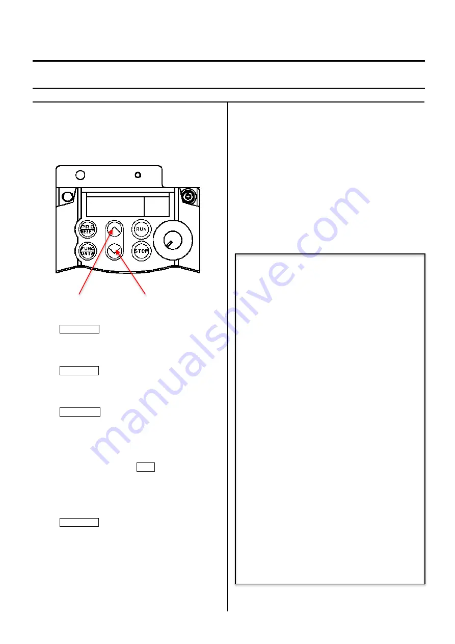
6. Press up key and function code is displayed.
Select the function code whose parameter you
would to change.
(Press down key and the function code returns to the
previous code.)
The following table shows function codes, setting details, and
factory default setting. Function other than described below
are initial setting of inverter.
Refer to the next clause for the method of initial setting.
Code Function
→
Setting
F00 Prohibition of change
→
1 (Protect)
F01 Frequency set mode
→
1
F02 Drive / Operation
→
1
F03 Maxmum frequency
→
100.0
F05 Base frequency voltage
→
200
F07 Acceletion time 1
→
1.2
F08 Deceletration time 1
→
0.7
F09 Torque boost
→
11.0
F11 Motor thermal protection
→
2.30
F15 Upper limit freq. limiter
→
100.0
F20 DC brake. Starting freq.
→
1.5
F21 DC braking current
→
20
F22 DC braking time
→
1.0
F23 Start frequency
→
0.5
F26 Carrier frequency
→
6
F27 Tone
→
1
F37 Load selection
→
1
C05 Multi stage frequency
→
2.6
C33 Analog input filter
→
0.05
C34 Analog input adjustment
→
50.0
C50 Bias frequency
→
3.0
P02 Motor capacity
→
0.40
P03 Motor caacity current
→
2.30
Up key
Down key
Содержание HCR3-1502
Страница 1: ... Maintenance Manual for Embroidery Machine HCR3E SERIES Version 1 2 HappyJapan Inc ...
Страница 104: ...105 4 7 3 Adjustment of timing detecting unit 8 Finally put the cover back on ...
Страница 107: ...107 ...
Страница 172: ...172 E7 Electric system diagram E7 1 Pulse motor driver PMD wiring ...
Страница 173: ...173 E7 2 Pulse motor driver PMD setup ...
Страница 174: ...174 E7 3 Inverter wiring ...
Страница 175: ...175 E7 4 Electrical connection diagram ...
Страница 176: ...176 ...
Страница 177: ...177 ...
Страница 178: ...178 E7 5 List of electrical connection diagram ...
Страница 179: ...179 ...
Страница 180: ...180 E7 6 Explanation of function clrcuit board HCD8122 LCD CE MX Board Ass y ...
Страница 181: ...181 HCD8116 TP SW Circuit Board Ass y CN No Function CN1 Switch output LED input ...
Страница 182: ...182 HCR8121 CONT R2 Circuit Board Ass y ...
Страница 216: ...2018 9 HappyJapan Inc 9 5 TAITO 2 CHOME TAITO KU TOKYO JAPAN TEL 81 3 3834 0711 FAX 81 3 3835 8917 ...


