background image

16

Hangar 9 33% Pawnee 80cc ARF

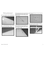
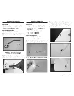
Note

: Always use threadlock on metal-to-metal 

fasteners to prevent them from vibrating loose.




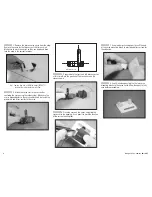
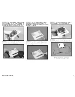
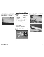
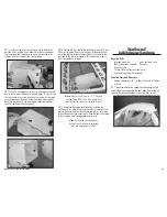
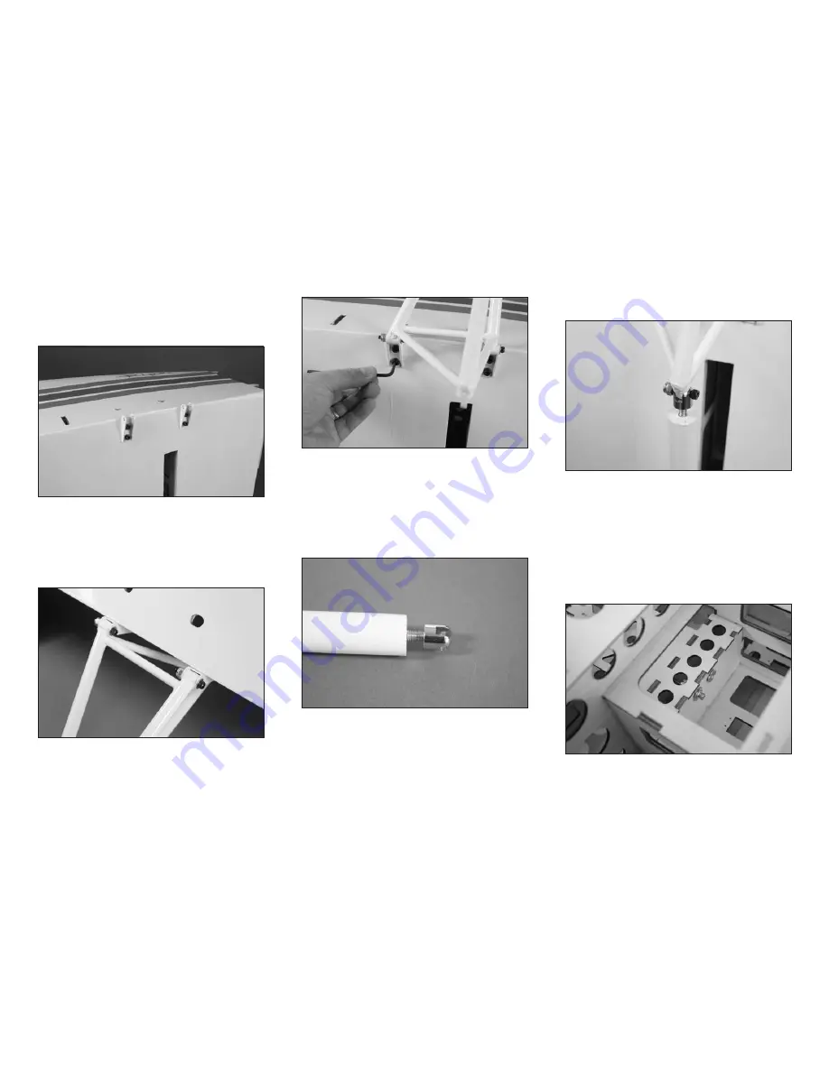
3. Use four 8-32 x 3/4-inch socket head cap screws 

and four #8 washers to attach the two landing gear brackets 

to the bottom of the fuselage. Leave the screws slightly 

loose so the gear can be installed. Tighten the screws using 

a 1/8-inch hex wrench.




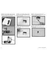
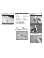
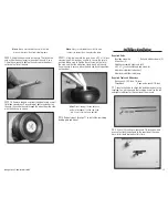
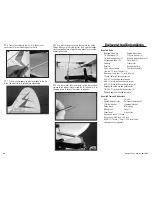
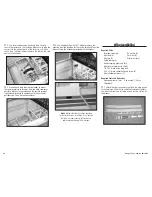
4. Use two 8-32 x 1-inch socket head cap screws, 

four #8 washers and two 8-32 lock nuts to attach the main 

landing gear to the brackets. Use a 1/8-inch hex wrench and 

11/32-inch open-end wrench to tighten the hardware. Make 

sure not to over-tighten the hardware as the gear must move 

freely in the brackets.




5. Fully tighten the screws that secure the landing gear 

brackets to the fuselage at this time using a 1/8-inch hex 

wrench. Double-check that the gear can still move freely in 

the brackets. If not, adjust the hardware as necessary.

Note

: Always use threadlock on metal-to-metal 

fasteners to prevent them from vibrating loose.




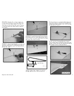
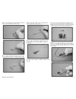
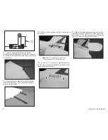
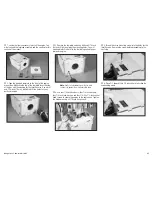
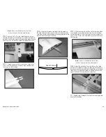
6. Thread the shock end on the shock. Screw the end 

on so the threads are flush to the inside of the bracket. You 

must use threadlock on the shock end to prevent it from 

vibrating loose over time.




7. Attach the shock end to the main landing gear 

using an 8/32 x 1-inch socket head cap screw and 8/32 lock 

nut. Use an open-end 11/32-inch wrench and 1/8-inch hex 

wrench to tighten the hardware. Check to make sure the 

shock can pivot on the gear, and if not, adjust as necessary 

until if can move freely.

Note

: Always use threadlock on metal-to-metal 

fasteners to prevent them from vibrating loose.




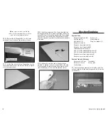
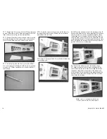
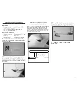
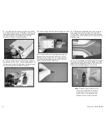
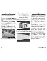
8. Slide a #8 lock washer, then a #8 washer on an  

8/32 x 2-inch socket head cap screw. Slide the screw 

through the bushing, then on through the hole in the top of 

the shock. The screw then threads into a blind nut that has 

been installed in the fuselage. Tighten the screw using a  

1/8-inch hex wrench.

Содержание 33% Pawnee 80cc ARF

Страница 1: ...33 Pawnee 80cc ARF Assembly Manual ...

Страница 2: ...33 4 inch 95mm Notice All instructions warranties and other collateral documents are subject to change at the sole discretion of Horizon Hobby Inc For up to date product literature visit http www horizonhobby com and click on the support tab for this product Meaning of Special Language The following terms are used throughout the product literature to indicate various levels of potential harm when ...

Страница 3: ...Batteries When used improperly lithium polymer batteries are significantly more volatile than alkaline or Ni Cd Ni MH batteries used in RC applications Always follow the manufacturer s instructions when using and disposing of any batteries Mishandling of Li Po batteries can result in fire causing serious injury and damage Small Parts This kit includes small parts and should not be left unattended ...

Страница 4: ...gine Zenoah GT80 Twin Cylinder ZENE80T 24 Diameter Gas Series Prop A Pitch VSS2401 Spinner TRUTT 3752 B M DA100 Transmitter Requirements This model requires a minimum of a 5 channel radio to operate all the functions of your aircraft We suggest the following radio systems available through Horizon Hobby or your local hobby distributor JR 9503 JRP2930X JR 11X JRP1100X Spektrum DX8 SPM8800 Spektrum ...

Страница 5: ...r and receiver connect Aileron and Flap Servo Installation Required Parts Wing panel right and left Ball end with hardware 4 Control horn long 2 Control horn short 2 8 32 flanged nut 4 Servo with hardware 4 Receiver Receiver battery Transmitter Aluminum servo arm 11 2 inch 38mm 4 18 inch 457mm servo extension 2 3 inch 152mm servo extension 2 Servo hardware 4 4 40 x 2 inch adjustable link 2 4 40 x ...

Страница 6: ... arm is perpendicular to the servo centerline Also install the grommets and brass eyelets in the servo Align Perpendicular 5 Prepare both the right and left aileron servos at this time Note the position of the servo horn on the servos shown 6 Place the servo on the cover centering the servo arm in the opening Use a pencil to mark the location of the servo mounting tabs 7 Use medium grit sandpaper ...

Страница 7: ...ewdriver to thread a servo mounting screw into each of the holes to cut threads in the surrounding wood Remove the screw before proceeding to the next step 12 Apply 2 3 drops of thin CA in each hole to harden the surrounding wood Allow the CA to cure before proceeding 13 Use four servo mounting screws and a 1 Phillips screwdriver to secure the servo in position 14 Use string or dental floss to sec...

Страница 8: ...mm wood screw into each of the holes to cut threads in the surrounding wood Remove the screw before proceeding to the next step 17 Apply 2 3 drops of thin CA in each hole to harden the surrounding wood Allow the CA to cure before proceeding 18 Tie the string to the end of the servo extension Use the string to pull the servo extension through the wing to the opening for the flap servo 19 Secure the...

Страница 9: ... screw for the aileron until it is 11 8 inch 29mm from the control surface as shown Use the short control horn for the aileron and the long control horn for the flaps Drawing not to scale 11 8 inch 28 5mm 23 Repeat Steps 2 through 22 to install the remaining aileron servos as well as the flap servos 24 Install the 4 40 x 3 inch adjustable link between the control horn and ball end With the servo c...

Страница 10: ...ts to the radio 29 Optional A clear lens and a string have been provided if a lighting system is to be installed in the wing Use canopy glue to secure the lens to the wing to either cover the opening or to finish off the lighting system Wing Strut Installation Required Parts Wing panel right and left Strut pin 6 Strut pin clip 6 Safety tubing 6 4 40 lock nut 4 Wing strut support 2 Wing strut mount...

Страница 11: ...et head cap screw and 4 40 lock nut Use 1 4 inch nut driver and 3 32 inch hex wrench to tighten hardware Make sure the airfoil on strut matches wing and jury strut fitting faces to wing 5 Attach short wing strut to front fitting with 4 40 x 5 8 inch socket head cap screw and 4 40 lock nut Use 1 4 inch nut driver and 3 32 inch hex wrench to tighten hardware Make sure the airfoil on strut matches wi...

Страница 12: ... inch 610mm servo extension 36 inch 915mm servo extension 3 4 40 x 1 2 inch socket head cap screw 3 2mm x 8mm sheet metal screw 8 Aluminum Servo Arm 3 inch 152mm Aluminum Servo Arm 11 2 inch 38mm 2 Required Tools and Adhesives Crimping tool Phillips screwdriver 1 Fuel tubing Nut driver 1 4 inch Pliers Threadlock Thin CA Hex wrench 3 32 inch 1 Locate the items necessary to install the elevator and ...

Страница 13: ...ll end To make sure the fitting is secure turn the fitting 12 rotations in the ball end 8 Repeat steps 3 through 7 to prepare a second ball end and cable 9 Use a 3 32 inch hex wrench and 1 4 inch open end wrench to secure the two ball ends to the rudder servo arm Position the ball ends so they are 11 4 inch 31mm from the center of the horn or in the first hole in from the end 10 Use string or dent...

Страница 14: ...e to harden the surrounding wood 16 Mount the elevator servos in the fuselage using a 1 Phillips screwdriver and the screws supplied with the servos The servos arms can then be installed through the side of the fuselage Access the pinch bolts on the servo horns by using the radio to move the servo arms 45 degrees to gain access through the slot in the fuselage Make sure the servo leads fall throug...

Страница 15: ... nut 6 8 washer 16 8 lock washer 2 8 32 x 3 4 inch socket head cap screw 10 8 32 x 1 inch socket head cap screw 4 8 32 x 2 inch socket head cap screw 2 6 32 x 1 4 inch setscrew 2 Wheel collar with setscrew 2 Main landing gear right and left Required Tools and Adhesives Threadlock Light machine oil Flat blade screwdriver Hex wrench 1 5mm 5 64 inch 1 8 inch Open end wrench 11 32 inch 1 Locate the it...

Страница 16: ...ve freely in the brackets If not adjust the hardware as necessary Note Always use threadlock on metal to metal fasteners to prevent them from vibrating loose 6 Thread the shock end on the shock Screw the end on so the threads are flush to the inside of the bracket You must use threadlock on the shock end to prevent it from vibrating loose over time 7 Attach the shock end to the main landing gear u...

Страница 17: ...of the axle and that the wheel can rotate freely on the axle Once the axle is secure place the hub cap back in position on the wheel Hint Place a drop of silicone adhesive on the inside edge of the hub cap if you find it is not secure when in position 12 Repeat steps 3 through 11 to install the remaining landing gear and wheel Stabilizer Installation Required Parts Fuselage assembly Ball end with ...

Страница 18: ... in the photo below 5 Slide the stabilizer assembly into the slot at the rear of the fuselage Note Always use threadlock on metal to metal fasteners to prevent them from vibrating loose 6 Use two 8 32 x 11 4 inch socket head cap screws and two 8 washers to keep the stabilizer half in position Do not tighten the screws at this time 7 Slide the remaining stabilizer into position Start the screws tha...

Страница 19: ...he elevator Thread an 8 32 flanged nut on the screw While using a flat blade screwdriver to hold the screw thread the control horn on the screw Note Always use threadlock on metal to metal fasteners to prevent them from vibrating loose 3 Use an 11 32 inch open end wrench to tighten the nut against the elevator to secure the screw We recommend using 30 minute epoxy on the screw as described in the ...

Страница 20: ...ts Fuselage assembly Metal clevis 16 Silicone clevis retainer 16 4 40 nut 16 Brass strut fitting 14 4 40 lock nut 6 4 washer 12 4 40 x 1 inch socket head cap screw 6 4 40 x 115 8 inch threaded rod 6 4 40 x 117 8 inch threaded rod 2 Required Tools and Adhesives Hex wrench 3 32 inch Threadlock Pliers Open end wrench 3 16 inch 1 4 inch 1 Locate the items necessary to install the tail struts You will ...

Страница 21: ...117 8 inch threaded rods are used on the underside of the stabilizer toward the rear of the fuselage Once all the rods are installed use a 3 16 inch open end wrench to tighten the 4 40 nuts against the clevises to keep them from moving Slide the clevis retainer over the clevises to keep them from opening accidentally in flight Rudder Preparation Required Parts Rudder 8 32 flanged nut 2 Rudder till...

Страница 22: ... of the rudder Use a felt tipped pen to mark the locations for the two mounting screws 6 Use a pin vise and 1 16 inch 1 5mm drill bit to drill the two holes for the tiller arm mounting screws 7 Use a 1 Phillips screwdriver to thread a 4 x 5 8 inch sheet metal screw in each of the holes drilled in the previous step to cut threads in the surrounding wood Remove the screw and apply 2 3 drops of thin ...

Страница 23: ...p epoxy from entering the hinge which could restrict their movement 3 Place the hinges in the rudder When positioned to full throw they will be perpendicular to the hinge line They also will be inserted so the hinge point is aligned with the hinge line of the rudder Use a hobby knife and 11 blade to trim the rudder as necessary to fit the hinges 4 Use a toothpick and 30 minute epoxy to glue the hi...

Страница 24: ...bly Engine mount box 1 4 20 blind nut 4 1 4 inch washer 4 1 4 inch lock washer 4 Ball end with hardware 2 4 tapered washer 5 Foam disk 5 Cowling Transmitter Receiver Receiver battery Servo with hardware Fuel tank assembly Tie wrap 12 inch 305mm 2 Aluminum servo arm 11 2 inch 38mm 18 inch 457mm servo extension 4 40 x 13 4 inch adjustable linkage 4 40 x 3 4 inch button head cap screw 4 40 x 1 2 inch...

Страница 25: ...drill and 5 16 inch 8mm drill bit to enlarge the mounting holes You will also need to drill a hole for the fuel tubing suited to your particular engine Note Always use threadlock on metal to metal fasteners to prevent them from vibrating loose 4 Use four 1 4 inch blind nuts four 1 4 inch washers four 1 4 inch lock washers and four 1 4 20 x 11 4 inch socket head screws to secure the engine to the e...

Страница 26: ...sks four 4 40 x 1 2 inch button head screws and one 4 40 x 3 4 inch button head screw Note that the tapered washers will have the cone facing out toward the head of the screw 11 Slide the cowl into position and secure it using the screws prepared in the previous step The longer 4 40 x 3 4 inch screw is used to secure the cowl at the top center of the cowl Use a 5 64 inch hex wrench to tighten the ...

Страница 27: ...ming loose in flight Note We use a Fuel Filler with a T Fitting and Overflow Fitting HAN116 to allow fueling of the model without the necessity of removing the cowl 16 Complete the engine installation by installing the mufflers and any other accessories necessary to operate your engine Place the cowl on the airframe and trim as necessary to clear the exhaust and accessories Once the cowl is secure...

Страница 28: ...e switch harness Mount the harness using the hardware provided with the harness Note Multiple locations have been provided for the switch harness installation Use a location that best suits your radio installation battery and receiver positioning in the fuselage Wing Installation Required Parts Fuselage assembly 8 washer 4 Strut end 4 4mm nut 4 Strut pin 4 Strut pin clip 4 Safety tubing 4 Wing ass...

Страница 29: ...e as forcing it could cause damage to the wing Note the joiner faces up toward the top of the wing Top of airframe 5 Slide the wing into position on the fuselage Make sure to guide any wiring from the wing into the fuselage so the wing panel will rest tightly against the fuselage Use two 1 4 20 x 2 inch nylon wing bolts to secure the wing to the fuselage Note Always use threadlock on metal to meta...

Страница 30: ...he cover over the battery compartment Control Throws Setting the control throws for your model does require some attention to detail To correctly set the throws it is highly suggested to use the following procedure to achieve the greatest mechanical advantage from your servos 1 Determine the maximum amount of control surface throw from the throws listed Use the high rate throws to set the maximum ...

Страница 31: ...eck the radio installation and make sure all the control surfaces are moving correctly i e the correct direction and with the recommended throws Test run the engine and make sure it transitions smoothly from idle to full throttle and back Also ensure the engine is tuned according to the manufacturer s instructions and it will run consistently at full throttle when adjusted Check all the control ho...

Страница 32: ...a final control check before advancing the throttle slowly The Pawnee has a lot of development that went into the undercarriage and it is designed so that it will track fairly straight with a small amount of right rudder Continue to advance the throttle to 100 power until flying speed is achieved As mentioned the Pawnee will want to fly so be ready for it to lift off quicker than you would expect ...

Страница 33: ...urchaser or user are not prepared to accept the liability associated with the use of the Product purchaser is advised to return the Product immediately in new and unused condition to the place of purchase Law These terms are governed by Illinois law without regard to conflict of law principals This warranty gives you specific legal rights and you may also have other rights which vary from state to...

Страница 34: ...05 Fieldstone Rd Champaign Illinois 61822 USA productsupport horizonhobby com 877 504 0233 Online Repair Request visit www horizonhobby com repairs All other products Horizon Product Support 4105 Fieldstone Rd Champaign Illinois 61822 USA productsupport horizonhobby com 877 504 0233 United Kingdom Horizon Hobby Limited Units 1 4 Ployters Rd Staple Tye Harlow Essex CM18 7NS United Kingdom sales hor...

Страница 35: ...h comparable standards B RADIO CONTROL RC 1 All pilots shall avoid flying directly over unprotected people vessels vehicles or structures and shall avoid endangerment of life and property of others 2 A successful radio equipment ground range check in accordance with manufacturer s recommendations will be completed before the first flight of a new or repaired model aircraft 3 At all flying sites a ...

Страница 36: ...ar9 com The Spektrum trademark is used with permission of Bachmann Industries Inc Hangar 9 UltraCote Evolution and JR are trademarks or registered trademarks of Horizon Hobby Inc All other trademarks service marks and logos are the property of their respective owners ...

Отзывы: