background image

.46 EP ARF

READ THROUGH THIS MANUAL

BEFORE STARTING CONSTRUCTION.

IT CONTAINS IMPORTANT INSTRUCTIONS 

AND WARNINGS CONCERNING THE 

ASSEMBLY AND USE OF THIS MODEL.

WEIGHT

4.6– 4.7lbs [2064–2133g]

WING LOADING

16– 17 oz/ft

2

 [51– 52 g/dm

2

]

RADIO

4 – 5 channels

Tow e r 
Hobbies

®


guarantees 
this kit to be 
free from defects 
in  both  material  and 
workmanship at the 
date of purchase. This 
warranty does not cover any 
component parts damaged by 
use or modification. In no case shall 
Tower Hobbies’ liability exceed the 
original cost of the purchased kit. Further, 
Tower Hobbies reserves the right to change 
or modify this warranty without notice.

In that Tower Hobbies has no control over the final 
assembly or material used for final assembly, no 
liability shall be assumed nor accepted for any damage 
resulting from the use by the user of the final user-assembled 
product. By the act of using the user-assembled product, the 
user accepts all resulting liability.

If the buyer is not prepared to accept the liability associated with the 
use of this product, the buyer is advised to return this kit immediately in 
new and unused condition to the place of purchase.

To make a warranty claim send the defective part or item to Hobby Services at 
the address below:

Hobby Services • 3002 N. Apollo Dr.  Suite 1 • Champaign IL  61822 • USA

Include a letter stating your name, return shipping address, as much contact information as 
possible (daytime telephone number, fax number, e-mail address), a detailed description of 
the problem and a photocopy of the purchase receipt. Upon receipt of the package the problem 
will be evaluated as quickly as possible.

WA

R

R

A

N

TY

TOWA2040 v1.1

© 

2017 Tower Hobbies.

®

  A subsidiary of Hobbico, Inc. 

®

®

TOWER HOBBIES

Champaign, Illinois

 (217) 398-8970 ext. 6

WINGSPAN

47.6 in [1210mm]

WING AREA

630.8 in

2

 [40.7 dm

2

]

LENGTH

48.1 in  [1222mm]

[email protected]

I N S T R U C T I O N   M A N U A L

POWER

Glow: .46 cu.in. 2-stroke

Electric: 1.70 in [42mm] diameter,

925 W, Hitec Energy Sport 80 ESC

Содержание Uproar V2 .46 EP ARF

Страница 1: ...user assembled product the user accepts all resulting liability If the buyer is not prepared to accept the liability associated with the use of this product the buyer is advised to return this kit immediately in new and unused condition to the place of purchase To make a warranty claim send the defective part or item to Hobby Services at the address below Hobby Services 3002 N Apollo Dr Suite 1 Ch...

Страница 2: ...this manual Other accessories for a glow engine 1 4 6 4mm R C foam rubber HCAQ1000 Fuel tubing GPMQ4131 Suitable propeller for your engine Brushless Electric Motor The electric setup for the Uproar V2 is straightforward a Great Planes Electrifly RimFire 32 on a 13 x 8 E prop with a 80A ESC powered by a 4S 3800mAh LiPo A Hitec Energy Sport 80 ESC is illustrated in the instruction manual A 14 x 7E p...

Страница 3: ...ay be required for tightening and re bonding the covering to the model that may have loosened between the time the plane was manufactured and the time the model was removed from the box The 21st Century iron is preferred because of its long cord contoured shoe and precisely adjustable temperature range Coverite 21st Century Sealing Iron COVR2700 Coverite 21st Century Cover Sock COVR2702 KIT INSPEC...

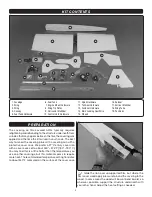
Страница 4: ... recommended temperature setting translates to about 340oF measured on the surface of the cover sock 1 Glide the iron over unsupported film but where the film is over wood apply pressure to bond the covering to the wood In some areas the wood will bow or bend inward so wherever possible support the structure underneath with your other hand Adjust the heat setting as needed KIT CONTENTS 1 Fuselage ...

Страница 5: ...g up epoxy when dampened with denatured alcohol 4 NOTE All machine thread screws that thread into metal hex nuts blind nuts wheel collars etc should be lightly wetted with threadlocker 5 NOTE The procedure for preparing the holes in wood for all wood screws is as follows A Drill the hole with the drill specified in the step B Install then remove the screw to set the threads C Add a drop or two of ...

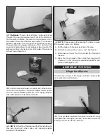
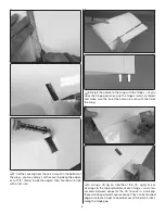
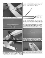
Страница 6: ... as you close the hinge gap make sure the hinges remain centered and make sure the tip of the aileron is even with the tip of the wing 4 Using a CA tip on a bottle of thin CA apply five or six drops to the top and bottom of each hinge wait a few seconds between drops for the CA to soak in And keep those small paper towel squares handy They can be touched edge wise to the hinges to absorb excess CA...

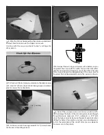
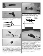
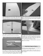
Страница 7: ... the servo to your receiver with a battery so you can power the servo with the radio Turn on the transmitter and the receiver Don t forget to center the trims and sub trims in your transmitter programming Fit a servo arm to the servo that will be perpendicular to the servo as shown 5 Cut off the unused servo arms and use a 49 073 drill to enlarge the holes in the remaining arm Even though the push...

Страница 8: ...king plate on the top of the aileron 9 With the aileron and servo arm centered mark the pushrod where it crosses the hole in the servo arm 90 Degree Pushrod Connector 1 16 1 6mm 10 Make a 90 degree bend in the wire at the mark connect the pushrod to the servo arm with a 90 degree pushrod connector and then cut off the excess wire 11 As noted and pictured on page 5 remove the servo mounting screws ...

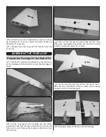
Страница 9: ...ribed on pages 4 and 5 2 Cut the covering from the fuselage over the rudder pushrod exit and both elevator pushrod exits and from the stab and fin slots Remove the temporary filler block from the stab slot 3 Also cut the covering from both sides over the wing tube holes the alignment peg holes the slots for the wing retainers and for the aileron servo wires 4 Cut the covering from the stab for the...

Страница 10: ...lizer and End of Fuselage Align 8 Make certain the trailing edge of the vertical stabilizer aligns with the aft end of the fuselage Otherwise the leading edge of the rudder will not contact both parts causing a hinge gap 9 The stab is pretty much locked in and self aligned with the fuselage but there is a little free play If striving for perfection you could rotationally align the stab as follows ...

Страница 11: ...10 Use a fine point felt tip pen to mark the base of the fin onto the top of the fuselage 11 Also mark the top and bottom of the fuselage onto the top and bottom of the stab 12 Cut the covering from the top of the fuselage approximately 1 16 1 6mm inside the fin marks being cautious not to cut into the wood Wipe away the ink lines with a paper towel square dampened with denatured alcohol Then remo...

Страница 12: ...ly 1 4 oz of 30 minute epoxy Apply epoxy to the top and bottom of the stab over the pinholes aligned with the fuselage sides and to all other joining parts of the fuselage and fin 3 Slide the stab into position then add the fin If you ve cut up balsa sticks use them to wipe away most of the epoxy followed by paper towel squares dampened with denatured alcohol Double check alignment place the weigh...

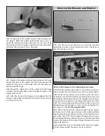
Страница 13: ...in the elevators to the stab with the hinges and permanently glue them in with thin CA If you ve poked pinholes in one side of the covering over the elevators be sure to put those sides down 3 Make both elevator pushrods the same way you made the aileron pushrods thread the clevises onto two 27 3 4 705mm threaded one end pushrods connect the clevises with silicone retainers to the pushrods and con...

Страница 14: ...L bend for a pushrod keeper as shown Refer to this image for the following three steps 2 Place the elevator and rudder servos in the servo tray as shown but do not mount the servos until instructed to do so 3 Hook up the rudder and elevators with the same techniques used for the ailerons centering the servos with the radio on finding the servo arm 90 degrees to each servo cutting off the unused ar...

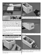
Страница 15: ... the pushrod link to make sure everything operates smoothly Make any adjustments necessary We ll mount the on off switch if used and receiver after the engine motor has been mounted INSTALL THE POWER SYSTEM Mount the Brushless Motor Skip to page 16 if installing a glow engine 1 Push a pin or a small nail into the four X marks in the firewall that mark the location of the holes for the mounting scr...

Страница 16: ...motor shaft that protrudes out the back of the motor 8 Connect the ESC to the motor and place the ESC in the compartment aft of the battery compartment ahead of the wing tube Guide the signal wire from the ESC over the wing tube into the radio compartment 9 Test fit the battery in the battery compartment Arrange the battery wires and make any adjustments necessary Skip ahead to Final Radio Install...

Страница 17: ...mount with engine to the firewall with four M4 x 25 Phillips screws and M4 lock washers and flat washers Use a Great Planes Dead Center hole locator to mark the rear engine mount screw holes onto the engine mount 6 Before removing the engine from the mount to drill the rear two mounting screw holes sight down a location on the firewall for the throttle pushrod and guide tube There is already anoth...

Страница 18: ... nuts Hook Up the Throttle 1 Guide the throttle pushrod guide tube through the hole you drilled in the firewall through the hole in the former in the fuel tank compartment and up to the throttle servo location Cut the guide tube to the correct length then glue it into place See the pictures on the next page for reference 2 Mount the throttle servo to the throttle servo mount 3 Fit then glue the th...

Страница 19: ...screw lock body with pliers so the set screw can be tightened thoroughly Install the Fuel Tank 1 Fit a 3 75mm piece of medium fuel line not included onto the straight pickup tube in the fuel tank stopper Then add the clunk to the line 2 Fit the stopper assembly into the tank with the vent tube pointing toward the top of the tank as shown Tighten the screw to compress the stopper and seal the tank ...

Страница 20: ... and will not get coated with fuel or exhaust Use the switch mounting plate as a template for cutting the slot and for drilling the holes for the switch 2 Connect 6 150 mm servo extensions to the receiver for the aileron servos Then use adhesive back hook and loop strips not included or other preferred method to mount the receiver Connect the servo wires and the on off switch 3 Position and secure...

Страница 21: ... 10 Phillips screws Mount the Tail Gear 1 Place the tail gear mount on the bottom of the fuselage with the vertical part of the tail gear wire centered over the rudder hinge line Use a pin or a wire to mark the mounting screw holes onto the bottom of the fuselage Then drill 1 16 1 6 mm holes through the marks 2 Enlarge the holes in the tail gear mount with a 3 32 2 4 mm drill 3 Fasten the tail gea...

Страница 22: ...ll be perpendicular with the rudder so the model will roll straight 8 Fasten the tail wheel to the gear with a collar on both sides Mount the Canopy Curved scissors for cutting out RC car bodies is best for trimming the canopy but regular scissors or a hobby knife may also be used Cutting off too much material can apply stress causing the canopy to crack so it s best to remove material in small in...

Страница 23: ...ron 7 Glue the canopy into place do not use CA because it will fog the canopy Just about any other kind of glue is okay but Zap Adhesives Formula 560 Canopy Glue is recommended because it washes off easily before it dries won t affect the plastic and dries clear 8 Position the canopy and hold it down with tape until the glue dries Attach the Side Force Generators The side force generators or tip p...

Страница 24: ...5 Right Left 2 1 2 64mm 36 5 Up Down 3 Adjust the control throws as necessary by using the programming in your transmitter and or moving the pushrods to holes farther out or in on your servo arms and or the control horns Note To achieve 3D throws the end points in your transmitter programming will have to be set to maximum or near the maximum value 4 If using the 3D throws a high volume of negativ...

Страница 25: ...ow such material in your face or eyes Keep your face and body as well as all spectators away from the plane of rotation of the propeller as you start and run the engine Keep these items away from the prop loose clothing shirt sleeves ties scarfs long hair or loose objects such as pencils or screwdrivers that may fall out of shirt or jacket pockets into the prop Use a chicken stick or electric star...

Страница 26: ...ou may overload the motor battery or ESC Battery Precautions Charge and store LiPo batteries in a safe place Never leave charging LiPo batteries unattended Before mounting the motor and setting up the ESC and battery readthefollowingimportantbatteryprecautions IMPORTANT If using multiple battery packs that are connected with an adapter never charge the batteries together through the adapter Always...

Страница 27: ...bide by the safety rules for the flying site I use and I will not willfully and deliberately fly my models in a careless reckless and or dangerous manner 5 I will not fly my model unless it is identified with my name and address or AMA number on or in the model Note This does not apply to models while being flown indoors 7 I will not operate models with pyrotechnics any device that explodes burns ...

Страница 28: ...to fly On high rates the Uproar V2 comes to life a little but still handles like any other regular sport model On 3D rates you better remain calm and be quick to react because the Uproar V2 responds quickly even with gobs of expo When time to land switch to the rates you are comfortable with The Uproar V2 can be landed perfectly but a few clicks of throttle until it s time to flair will help drag ...

Отзывы: