background image

HB 02 Birdroni Assembly Instuction Manual

Содержание HB-02 Birdroni

Страница 1: ...HB 02 Birdroni Assembly Instuction Manual ...

Страница 2: ...ed Parts Non 3D Printed Parts Before We get Started Kit Assembly Instructions Electronics Installation Instructions Page Number For this kit you will need the 3D printed parts and non 3D printed parts which come included The list of electronics that you will need include 50mm EDF without a lip ESC LiPo Battery Receiver and Transmitter You will also need the following common household tools scissor...

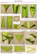
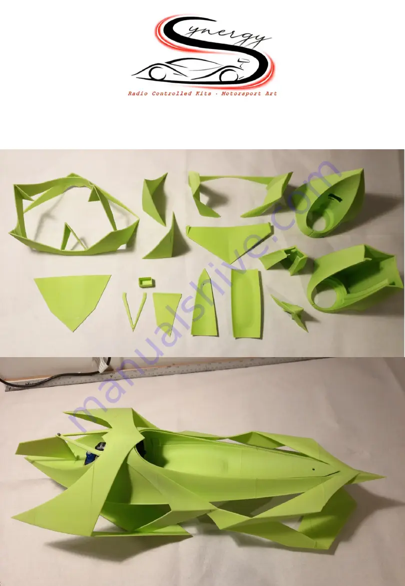
Страница 3: ...art 11 Rear hydro surface base Part 6 Rear Cover Piece Part 7 Stopper Part 10 Rear Hydro Surface Left Tip Part 12 Rear hydro surface bottom Part 13 Front Hydro surface base Part 14 Front hydro surface bottom Part 15 Rudder Part 16 Rudder Mount Please Note Your parts may differ slightly from the parts in the images shown please rest assured that you have the latest and correct parts 2 ...

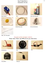
Страница 4: ...e kit Servo Motor Seal Glue and Activator Wire Cable Extensions M3 and M1 Bolts Wax Electronics Not Included in the Kit Please Note These may differer from your electronics LiPo Battery EDF ESC Transmitter Receiver Wire 1mm diameter 3 ...

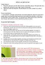
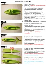
Страница 5: ...e sure not to apply too much glue so it doesn t overspill and cause an external glue line at the joint 3 Spray activator on the other face the one without the glue and wait for it to evaporate You can gently blow on it to make it evaporate faster this only takes a few seconds 4 Carefully press the two faces together ensuring you line them up correctly and hold the parts in this positions for aroun...

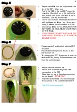
Страница 6: ...Test fit the faces which are to be bonded together notice the orientation in the picture and use the glue and activator to bond them together Ensure you follow the G A Guide instructions Step 3 Step 4 Prepare the parts shown part 1 and bonded hull piece Test fit the faces which are to be bonded together notice the orientation in the picture and use the glue and activator to bond them together Ensu...

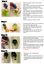
Страница 7: ...F WIRES ARE FACINGS DOWNWARDS AT THE REAR IT IS VERY IMPORTANT THAT YOUR EDF IS MOUNTED SECURELY SO PLEASE DO DOUBLE CHECK Step 6 Prepare parts 7 and the hull with the EDF mounted Place these in the groove closest to the EDF see arrow To remove your EDF if you want to use it in another RC kit simply pull this stopper out from the slot in the part Step 7 Prepare the wire extenders Attach wire exten...

Страница 8: ...y Notice the orientation of these parts relative to each other and place the servo housing inside of the rectangular hole at the rear of the hull Notice the flanges where the servo housing sits on top of place glue on them push the servo housing fully down and bond Ensure you follow the G A Guide instructions Prepare the parts shown servo mounted in part 8 and the yellow wax seal Take some wax sea...

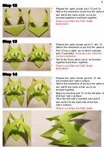
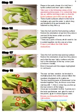
Страница 9: ... 10 and the bonded rear hydro surface Notice the orientation of parts in the picture and test fit the faces which are to be bonded together Begin by bonding part 10 to the left sede of thre rear hydro surface Once the left side is bonded take part 9 and bond it to the right side of the rear hydro surface Ensure you follow the G A Guide Step 12 Prepare the parts shown part 13 and 14 Notice the orie...

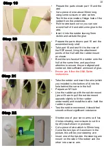
Страница 10: ...ed together do this one at a time Ensure you follow the G A Guide instructions Take the hull and the rear planing surface Notice the orientation of parts in the picture and slide the rear hydro surface onto the hull in the direction of the top arrow see photos on the left Brint it forward until the edges highlighted in red touch The rear surface needs to be bonded in multiple places this order ple...

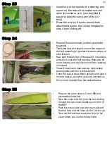
Страница 11: ...on to ensure they are aligned and centered Add sufficient ammount of glue Ensure you follow the G A Guide instructions Take the rudder and insert the wire which you installed to the bottom of it into the hole behind the servo in the hull Prepare an M1 bolt Line the rudder up with the rudder mount you will have to pull the rudder mount upwards slightly to fit the rudder underneath and install the b...

Страница 12: ...he glue and activator as this is more durable than the seal adhesive Prepare the parts shown Cover M3 bolt assembled bodyshell Take the cover and fit it onto the hull sliding it under the two cover holders jus in front of the EDF Push the cover back over the rear seal until the bolt hole and the insert in the hull line up Take the M3 bolt and screw the front of the cover down you can do this by ha...

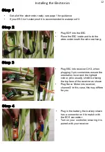
Страница 13: ...nto receiver CH 3 when plugging 3 pin connectors ensure the orientation is correct the lightest colour yello usually shoild be facing the top face of the receiver as shown Plug Servo Motor into receiver channel 2 in this case this may differe for you Installing the Electronics Step 4 Plug in the battery the battery shown has a connector on it to match with the ECS connector Turn on your controller...

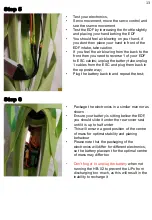
Страница 14: ...ery when not running the HB 02 to prevent the LiPo from discharging too much as this will result in the inability to recharge it Test your electronics Servo movement move the servo control and see the sservo movement Test the EDF by increasing the throttle slightly and placing your hand behing the EDF You should feel air blowing on your hand if you dont then place your hand in front of the EDF int...

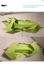
Страница 15: ...Step 7 Go out and enjoy yourself with your very own HB 02 Birdroni 14 ...

Отзывы: