Hameg HM8118 Скачать руководство пользователя страница 12

48

First-Time Operation

selected for this DUT, it will display in the center of the se-

lected range. Since the measurement error is defined as 
a percentage of the measurement range final value, the 

measurement error in the higher range goes up nearly by 
a factor of 2. Typically, the measurement error is increased 
accordingly in the nearest higher measurement range. If a 
component is removed from the test lead or measurement 
adapter during a measuring process in the continuous 
measurement mode, the automatically selected measure-
ment range and the automatically selected measurement 
function can be adopted by switching to the manual mea-
surement range selection (RANGE HOLD). This allows the 
measurement time during the measurement of many simi-
lar components to be reduced. 

4.5.1 Example of determining the measurement 

accuracy

The accuracy calculation is always based on the data sheet 

table (see fig. 4.5). 

To calculate the corresponding measu-

rement accuracy, the following component parameters are 
required (component operating point):

Component impedance at corresponding measurement
frequency

The measurement frequency.

As an example, a 10 pF capacitator with an impedance of 

15 MΩ at 1 kHz will be measured. In this case, the top row 

of the accuracy table is valid:

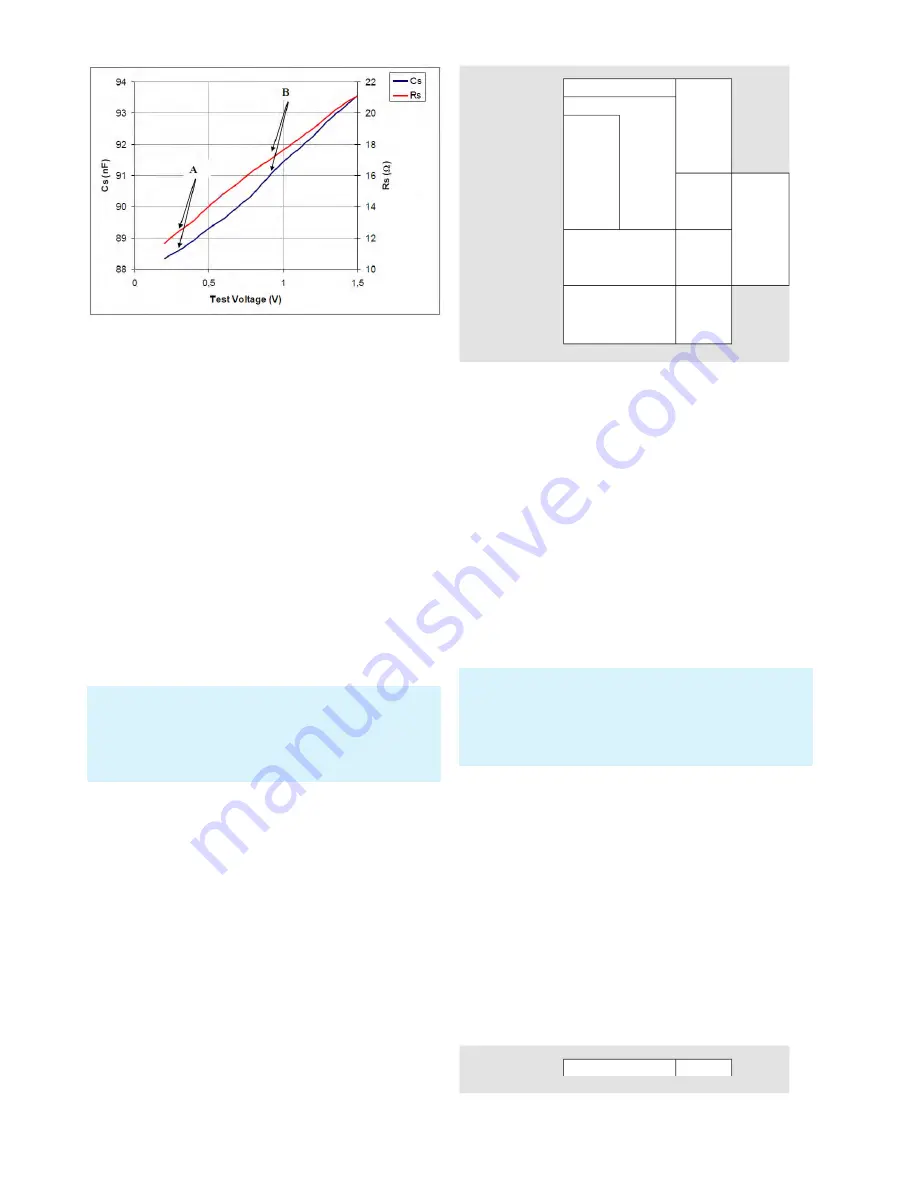
The accuracy decreases with the measurement voltage (test vol-
tage) because the signal / noise ratio decreases. Consequently, 
this leads to additional instabilities. The accuracy decreases at 
the same rate. If 0.5V is used as measurement voltage, for in-
stance, the base accuracy is one half.

Impedance:

  100 MΩ

4 MΩ

20 Hz

1 kHz

10 kHz

100 kHz

0,2% + I Z I / 1,5 GΩ

The actual measured series resistance includes all series 
resistances such as the component leads and the resis-
tance of series-connected foils in capacitors as well as die-
lectric losses; it is expressed by the dissipation factor DF. 
The equivalent series resistance (ESR) is frequency-depen-
dent according to the formula:

ESR  =  Rs  =  D/ωCs 

where ω „Omega“ = 2 π f (circular frequency) represents. 

Traditionally, the inductance of coils is measured in a series 
circuit; however there are cases where a parallel circuit will 
yield a better representation of the component. In small 
„air“ coils mostly the ohmic or copper losses are predomi-
nant , hence the series circuit is the proper representation. 
The core of coils with an iron or ferrite core may contribute 
most of the losses, the parallel circuit is to prefer here.

4.5  Measurement Accuracy

The measurement of impedance and phase angle is prone 
to a certain amount of inaccuracy. The measurement accu-

racy of a specific test point can be calculated based on the 
accuracy table in the data sheet (see fig. 4.5). Make sure 

you know the impedance of the corresponding component 
at the respective test point. No further information is requi-

red to calculate the accuracy. The base accuracy of 0.05% 

as indicated in the data sheet pertains only to the base ac-
curacy of the HM8118 bridge. The base accuracy only indi-
cates the general measurement uncertainty of the instru-
ment. The accuracy table describes the measurement ac-
curacy that additionally has be taken into account. 

The highest accuracy is ensured when the DUT value (= 
Device Under Test) is approximately centered in the mea-
surement range. If the next highest measurement range is 

Fig. 4.4: Example correlation Cs (or Rs) and test voltage

The resistance measurement always occurs in compliance with 
the method to apply voltage (AC) and measure the resulting cur-
rent. The only difference to L or C is that the phase angle is ne-
arly 0° (real resistance). A resistance measurement with DC is 
not intended.

Fig. 4.5: Table to determine the accuracy

Impedance:

 100 MΩ

4 MΩ

1 MΩ

25 kΩ

100 Ω

2.5 Ω

0,01 mΩ

20 Hz

1 kHz

10 kHz

100 kHz

0.2% + I Z I / 1.5 GΩ

0.05% + 

I Z I / 2 GΩ

0.1% + 

I Z I / 1,5 GΩ

0.5% + 

I Z I / 100 MΩ

0.2% + 

I Z I / 100 MΩ

0.1% + 1 mΩ / I Z I

0.3% + 1 mΩ / I Z I

0.2% +  

2 mΩ / I Z I 

0.5% +  

2 mΩ / I Z I 

0.5% +  

5 mΩ / I Z I

+

I Z I / 10 MΩ

Содержание HM8118

Страница 1: ...HM8118 Programmable LCR Bridge User Manual...

Страница 2: ...not leave the premises All signal connec tions must be shielded e g coax such as RG58 U With signal generators double shielded cables are manda tory It is especially important to establish good ground...

Страница 3: ...rement Range 51 6 5 Circuit Type 52 7 Instrument Functions 52 7 1 SETUP Menu 52 7 1 1 Measurement Frequency FRQ 52 7 1 2 Voltage LEV 53 7 1 3 Preload Bias Current BIAS 53 7 1 4 Measurement Range RNG 5...

Страница 4: ...fety reasons the instrument may only be operated with authorized safety sockets The power cord must be plugged in before signal circuits may be connected Never use the product if the power cable is da...

Страница 5: ...n the back panel has to be unplugged The product may only be opened by authorized and qualified personnel Prior to working on the product or before the product is opened it must be disconnected from t...

Страница 6: ...Cells and batteries must be recycled and kept separate from residual waste Cells and batteries must be recy cled and kept separate from residual waste Recharge able batteries and normal batteries tha...

Страница 7: ...ng the parallel equivalent circuit RANGE 17 AUTO HOLD Activating the automatic measurement range LED lights up or the range HOLD function 18 UP Range up 19 DOWN Range down Connectors 20 L CUR BNC sock...

Страница 8: ...38 L Q 1 Selection of the measurement function Induc tance and Quality factor Q resp entering numeric value 1 39 Z 7 Selection of the measurement function Im pedance Z and Phase angle resp entering nu...

Страница 9: ...be very low at this setting The smaller the loss angle the more the real world com ponents will come close to the ideal An ideal inductor has a loss angle of zero degrees An ideal capacitor also has a...

Страница 10: ...esistors will be measured using the parallel equivalent circuit 4 First Time Ope ration 4 1 Connecting the instrument Prior to connecting the instrument to the mains check whether the mains voltage co...

Страница 11: ...result of multiple possibly overlapping individual capacities inductances and impedances This can easily cause some misunderstandings especially with coils magnetic field eddy currents hysteresis etc...

Страница 12: ...d by the dissipation factor DF The equivalent series resistance ESR is frequency depen dent according to the formula ESR Rs D Cs where Omega 2 f circular frequency represents Traditionally the inducta...

Страница 13: ...only be displayed with an integrated binning interface HO118 Use the keys L R 2 36 C D 3 34 C R 4 32 R Q 5 30 to select the sub menus associated with the menu functions Depending on the function you...

Страница 14: ...elative measurement value deviation in percent Press the SELECT key 3 to use the SETUP and the set ting DEV_M for the main measurement value display and DEV_S for the secondary measurement value displ...

Страница 15: ...nts the instrument from constantly switching the measurement range if the measurement va lue is close to the switching threshold of a measurement range The following table shows the switching threshol...

Страница 16: ...be better suited as equivalent circuit diagram for the measurement circuit In the auto matic mode the bridge selects the serial equivalent circuit diagram for impedances below 1k and the parallel equ...

Страница 17: ...m i e after switching off the bias current it is required to wait for the coils to discharge before the component is disconnected from the measuring instrument During the discharge Please wait is show...

Страница 18: ...e RNG The measurement range can be selected automatically or manually If the measurement range is changed the inter nal measurement circuit replacement circuit will be mo dified and internal relays wi...

Страница 19: ...rigger event measurement has been triggered or the selected measurement function has been selected incorrectly lue via keypad confirm the entry by pressing the ENTER key or by pressing the knob again...

Страница 20: ...g HZ184 are used If the DUT ex hibits impedances of more than 25k at frequencies of more than 100kHz is is also recommended to use the GUARD function REF_S In the SETUP menu use the arrow keys 7 to s...

Страница 21: ...ithout components connected The short compensation is possible for impedances of up to 15 and resistances of up to 10 LOAD A compensation with adjustment compensation of a known load impedance is suit...

Страница 22: ...enter a value After en tering the value via keypad confirm the entry by pressing the ENTER key or by pressing the knob again The LOADM or LOADS function is not necessary for Hameg ac cessories In this...

Страница 23: ...FRQ function to choose the line frequency press the knob 6 editing mode and select the desired line frequency 50Hz 60Hz via knob Press the knob again to confirm the selection 7 3 6 Instrument Informat...

Страница 24: ...nt panel During a measure ment do not touch the component directly with hands or indi rectly with objects as this may distort the measurement results Always remove measurement accessories such as test...

Страница 25: ...rate via 4 wire con nection with LCR bridge HM8118 Measurable components Resistances coils or capacitators Frequency range 20 Hz to 200 kHz Test lead length approximately 35 cm Connectors BNC sockets...

Страница 26: ...he unknown state of the prema gnetized core The component to be measured is depen dent on the frequency as well as on the applied measure ment voltage The measuring instrument determines the values fo...

Страница 27: ...de termining the leakage inductance requires the secondary transformer side to be short circuited see fig 8 11 If the secondary side is short circuited the measured values of the primary side correspo...

Страница 28: ...easurement se tup are implemented it becomes necessary to perform a new compensation For more information about the OPEN SHORT compensation see chapter 7 2 8 5 Sorting Components with Option HO118 Bin...

Страница 29: ...nge for the sorting bins 0 5 and only the secondary parameters exceed the limit for sorting bin 6 7 General Fai lure BIN This sorting bin output is activated if the sorting does not apply to one of th...

Страница 30: ...sponds to TTL level and triggers with falling slopes It is protected against voltages of up to 15 volts For more information on the binning interface in the con text of the PIN and jumper assignment r...

Страница 31: ...E 488 controller control unit of a IEEE 488 bus system Any PC equipped with the corresponding plug in card can function as IEEE 488 controller If a IEC 625 cable must be used an appropriate plug in ad...

Страница 32: ...ort parallel processing of commands measuring instrument and if the instrument is ready to per form another measurement WAI The WAI command is a synchronization command that stops every subsequent com...

Страница 33: ...easurement circuit By de fault the automatic circuit type i 2 is selected Use i 0 The constant voltage CST V function must be switched on for measurements with bias current or external preload The err...

Страница 34: ...ative measurement value deviation REF_M for the main measurement value display if the measurement value de viation of the main measurement value display was previ ously activated via OUTP 1 or OUTP 2...

Страница 35: ...o 0 or if the automatic measurement mode AUTO is selected an error message is issued 10 3 Command List Binning Interface only with integrated binning interface HO118 XBIN The XBIN query queries the nu...

Страница 36: ...to 180 999 99 to 999 99 M 1 H to 100H N 0 95 to 500 Measurement conditions and functions Test frequency 20Hz to 200kHz 69 steps Frequency accuracy 100ppm AC test signal level 50mVrms to 1 5Vrms Resol...

Отзывы: