


Slide 80
Figure 9.1
9.
Drive
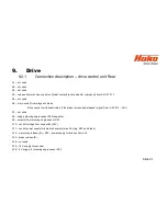
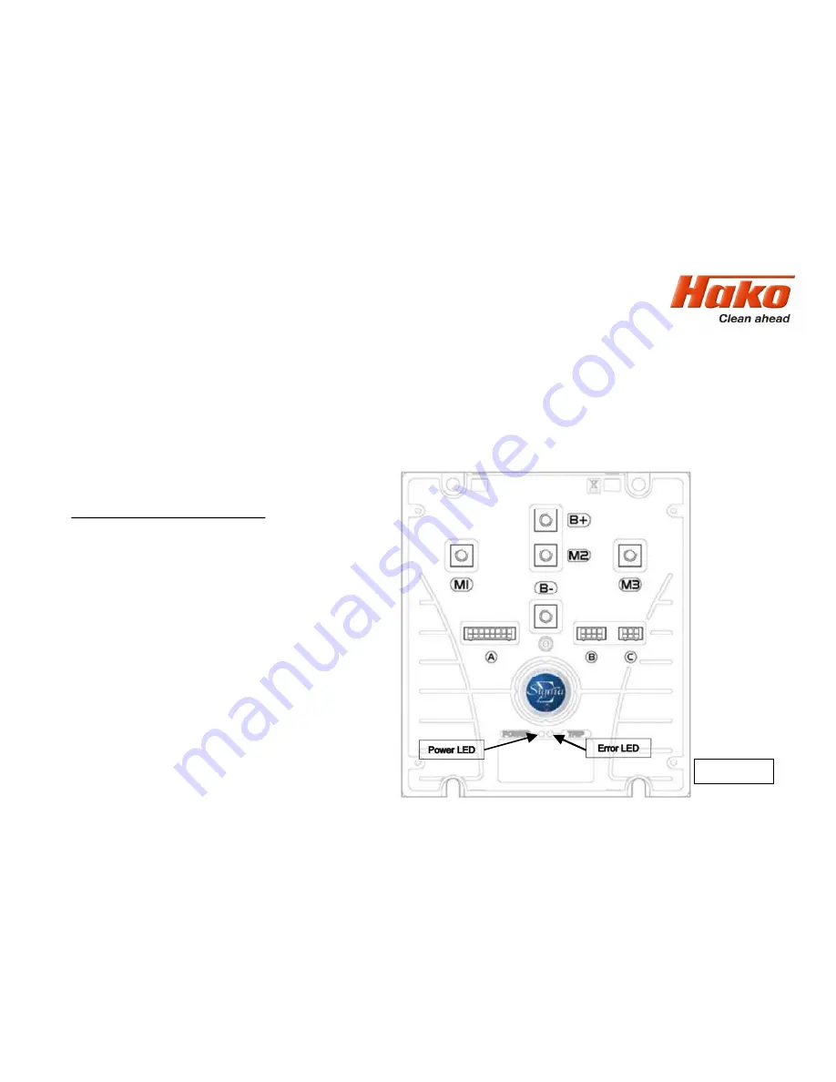
9.1 DMC drive control unit - Front
The DMC drive control unit features a diagnostic input. Unless clearly noted in the service
documents, changes to the preset values and parameters is generally
not
permitted. Currently,
only the diagnostics with flash codes for the LED indicator is used.
9.1.1 Connection description:
M1; M2; M3 – motor connections
B+; B- – battery power supply
A – control connections (16-pole)
B – programming plug CAN bus (8-pole)
C – motor feedback (6-pole)
(encoder and temperature)
Содержание Scrubmaster B260 R
Страница 64: ...Slide 64 Figure 7 2a Figure 7 2b 7 Mechanical components 7 1 Squeegee...
Страница 66: ...Slide 66 Figure 7 4 7 Mechanical components Height adjustment 7 1 Squeegee...
Страница 69: ...Slide 69 7 Mechanical components 7 2 1 Rotating brush heads contact pressure stages Figure 7 5 A B C...
Страница 100: ...180 130 170 150 120 Figure 9 5 Slide 100 9 Drive 9 2 4 Steering angle sensor...
Страница 108: ...Slide 108 10 2 Service alarm clock 3 3 1 1 The service alarm clock is set via the Hako diagnostic system...
Страница 119: ...Slide 119 13 Electrical components 13 2 Dash board A02 Position of connectors on Dash board A02...
Страница 121: ...Slide 121 14 Notes...


