


Slide 117
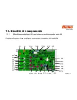
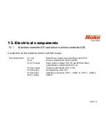
13. Electrical components
13.1
Machine controller A01 and slave machine controller A06
Connectors on the machine control unit A01
Connectors A01:
X1 / X2
Main Power supply plus and Minus from F02
X3/4 & X5/6
Power output brush motor 1 & 2 (M03 & M04)
X7/8 & X9/10
Power output suction motor 1 & 2 (M16 & M17)
X11 (6-pole)
connector lifting element squeegee and brush aggregat;
Side broom motors
X12 (20-pole)
small load output
X13 (12-pole)
24V output; X13.1/7 – power supply position recognision
lifting element brush aggregat;
X13.10/11 Relaiscontact enable drive control units
X14 (10-pole)
Input control voltage X14.1/6;
output Main contactor X14.2
USB- Socket X14.3/4/8/9
5V-supply solution tank filling level sensor X14.5
X15 (24-pole)
Analogus und digital inputs
X18 (8-pole)
CAN-Bus connections
X20 ( 6-pole)
Serial connector for communication Fleetrecorder
X22 (1-pole)
VGND
Содержание Scrubmaster B260 R
Страница 64: ...Slide 64 Figure 7 2a Figure 7 2b 7 Mechanical components 7 1 Squeegee...
Страница 66: ...Slide 66 Figure 7 4 7 Mechanical components Height adjustment 7 1 Squeegee...
Страница 69: ...Slide 69 7 Mechanical components 7 2 1 Rotating brush heads contact pressure stages Figure 7 5 A B C...
Страница 100: ...180 130 170 150 120 Figure 9 5 Slide 100 9 Drive 9 2 4 Steering angle sensor...
Страница 108: ...Slide 108 10 2 Service alarm clock 3 3 1 1 The service alarm clock is set via the Hako diagnostic system...
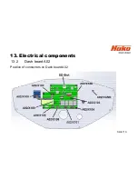
Страница 119: ...Slide 119 13 Electrical components 13 2 Dash board A02 Position of connectors on Dash board A02...
Страница 121: ...Slide 121 14 Notes...


