background image


5.52.693.00.01.00 


13 


12.3.1 

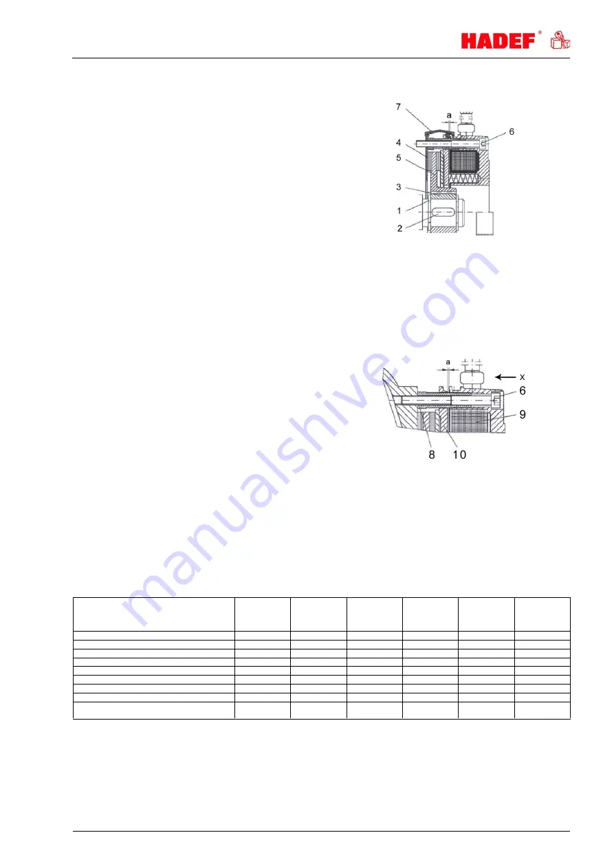
Assembling the brake 

1  Insert the retaining ring (1) into the shaft slot. 

2  Insert the feather key (2) into the motor shaft. 

3  Fix hub (3) with retaining ring (1). 

4  Assemble the friction plate (4) if existent. 

5  Push the rotor (5) onto the hub (3). 

6  Lock the magnet body with the 3 fastening 

screws (6). 

Set air gap “a” (refer to “adjusting the air gap”) 

8  Assemble the dust-protection ring (7) if 

existent. 

9Electric connection 


Illustration 9 


12.3.2 

Disassembly of the brake 

Disassembly is performed in reverse order to the assembly. 

12.3.3 

Adjusting the air gap 

View "X" on the brake. 

1  Loosen the locking screws (6) by half a turn. 

2  Turn the cap screws (8) into the magnetic body 

(9) anti-clockwise. 

3  By  turning  the  locking  screws  (6)  clockwise, 

move  the  magnetic  body  (9)  towards  the 
anchor  plate  (10)  using  a  feeler  gauge  until 
nominal air gap “a” is reached (see table). 

4  Unscrew the cap screws (8) from the magnetic 

body clockwise. 

5  Tighten the locking screws (6). 

6  Check  the  air  gap  again  and  re-adjust  if 

necessary. 


Illustration 10   


13 

Inspection 


13.1 

Periodic checks 

Independently from the regulations of the individual countries, lifting devices must be checked at least yearly 
by a qualified person or licensed qualified person regarding its functional safety.  


at 

commissioning 

daily 

checks 

1st maintenance 

after 

3 months 

Inspection 

Maintenance 

every 

3 months 

Inspection 

Maintenance 

every 

12 months 


check screw connections 


check the bearings 


check the trolley wheels 


check lubrication of the driving pinion 


buffers - check correct position and wear 


electric motor* - check the brake lining 


electric motor* - check the brake 


pneumatic motor* 


Have the equipment checked by an expert 

(periodic inspection) 


*as far as applicable 


14 

Service 


14.1 

Electric motor 

  For  the  motor  it  is  sufficient  to  keep  the  cooling  airways  clean  and  monitor  the  roller  bearing  and  its 
lubrication status. 

A high temperature fat must be used if the roller bearing is replaced. 


Содержание 32/20

Страница 1: ...onorail Trolley Type 32 20 as monorail push travel trolley R as monorail hand geared trolley H as monorail electric trolley E as monorail pneumatic trolley P as swivelling Trolleys Installation Operat...

Страница 2: ...Contents 1 Information 3 2 Safety 3 2 1 Warning notice and symbols 3 2 2 Duty of care of the owner 4 2 3 Requirements for the operating personnel 4 2 4 Appropriate use 5 2 5 Basic safety measures 5 3...

Страница 3: ...claims require adherence to all instructions in this manual Before delivery all products are packed properly Check the goods after receipt for any damage caused during transport Report any damage imm...

Страница 4: ...he device is only operated in a fault free fully functional condition and the safety components in particular are checked regularly to ensure that it is functioning properly The required personal prot...

Страница 5: ...ndication label in reactor containment vessels to transport people The device is not suitable for use on stages and in studios Persons must not stand under a suspended load NOTICE If the units are not...

Страница 6: ...o not throw or drop the equipment Use adequate means of transport Transport and means of transport must be suitable for the local conditions 3 2 Safety device for transport NOTICE Should a safety devi...

Страница 7: ...treme environmental impact is the regular use of the equipment 4 4 Important components Wheels Machined wheels with maintenance free roller bearings Profiled wheel surfaces for the use on all standard...

Страница 8: ...type leave a distance for the load hook It is important that the load hangs in the middle under the beam so that the two side plates are equally loaded The suspension eye 9 if existent for bigger load...

Страница 9: ...to adjust the beam flange width dismantle the safety screws 3 at one trolley side After adjustment of dimension X and installation on the beam install the safety screws 3 again and secure them with a...

Страница 10: ...nd chain Control buttons Control symbols shown are for optical information only and can vary depending on the control module Emergency stop Illustration 3 Arrow keys drive left right Illustration 4 Sy...

Страница 11: ...000 kg capacity and without motor driven trolleys of hoisting unit must be tested by a qualified person before putting into operation for the first time Hoists of 1000 kg capacity and up or with more...

Страница 12: ...and check the positions of the end stops 12 Maintenance 12 1 General All monitoring servicing and maintenance operations are to ensure correct functioning of the equipment they must be effected with u...

Страница 13: ...crews 8 from the magnetic body clockwise 5 Tighten the locking screws 6 6 Check the air gap again and re adjust if necessary Illustration 10 13 Inspection 13 1 Periodic checks Independently from the r...

Страница 14: ...the oiler of the maintenance unit Recommendation Should longer periods of standstill be foreseen insert some cm of oil into the air supply hose after the last use of the unit and let the motor run sho...

Страница 15: ...be changed completely If the unit is suitable for explosive atmospheres the motor must be returned to the manufacturer for repair Air gap is too large Re adjust the air gap If the unit is suitable fo...

Страница 16: ...rried out in accordance with environmental regulations 18 Additional documents 18 1 Electric wiring diagrams Electric wiring diagrams are attached to the consignment or included in the terminal box Ex...

Отзывы:

Похожие инструкции для 32/20