16
Specifications
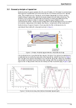
The oxygen partial pressure (pO
2
) is then linked to the corresponding phase-shift measurement
(
to build the sensor calibration curve (shown right in
). This curve is described by the
Stern-Volmer equation (shown left in
) where K
sv
is the indicator quenching constant (in
mbar
-1
) representing the quenching efficiency of the oxygen and thus the sensor sensitivity, f
0
is
a constant and
0
is the phase-shift at zero oxygen representing the unquenched fluorescence
decay time of the dye. The calibration curve thus relies on two parameters: the phase-shift at
zero oxygen and the luminescent spot sensitivity, K
sv
. The dissolved oxygen concentration is
then calculated with Henry’s law using the water solubility curve as a function of the
temperature.
2.3 Hardware description
The instrument hardware is made of one main board, and one measurement board for the
measurement channel (= the sensor).
The main board includes the controls for power, display, the touch screen, the barometric
sensor, the alarms, and communication ports. The measurement board performs measurements
and executes commands from the main board. It holds the "Analog output" and "Relays" that
send information to external systems.
A hardware watchdog is activated at program start up, to check that the system is not frozen
(i.e. infinite loop, system crash, etc.). If the watchdog is not refreshed by the software every
minute, the measurement display, the relays and the analog outputs are frozen for up to 2
minutes. Then the reset shuts down the instrument for 10 seconds and the start-up procedure is
performed. At the same time all the hardware (sensor, measurement board) are reset.
Figure 3 Stern-Volmer equation and calibration curve
Содержание ORBISPHERE K1200
Страница 1: ...DOC024 52 93022 ORBISPHERE Model K1200 Sensor and Model 510 Analyzer USER MANUAL 11 2017 Edition 12...
Страница 5: ...4 Table of Contents...
Страница 13: ...12 General Information...
Страница 39: ...38 Installation...
Страница 45: ...44 User Interface...
Страница 46: ...45 Section 5 View Menu Figure 34 View menu...
Страница 49: ...48 View Menu...
Страница 59: ...58 Calibration Menu...
Страница 60: ...59 Section 8 Inputs Outputs Menu Figure 40 Inputs Outputs menu...
Страница 62: ...61 Inputs Outputs Menu 8 4 Analog outputs Figure 41 Analog outputs menu...
Страница 69: ...68 Inputs Outputs Menu...
Страница 86: ...85 Section 11 Products Menu Figure 44 Products menu...
Страница 89: ...88 Global Configuration Menu...
Страница 90: ...89 Section 13 Services Menu Figure 46 Services menu Part 1...
Страница 91: ...90 Services Menu Figure 47 Services menu Part 2...
Страница 99: ...98 Maintenance and Troubleshooting...

