26
Installation
3.4.3 Connection panel (bottom of instrument)
Note:
The type of power cable connection will vary depending on the instrument specification.
Alternative instrument mounting procedure
When it is not convenient to work from the back of the panel, the instrument can be connected
before fitting in the panel.
1.
Install the panel support frame in the panel opening
2.
Slip the cables through the panel opening
3.
Remove the instrument cover
4.
Slip the cables through the instrument cover
5.
Slip the cables through the instrument back panel cable glands
6.
Connect the cables to the instrument electronic boards
7.
Tighten the cable glands
8.
Reinstall the instrument cover
9.
Install the instrument in the panel opening
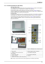
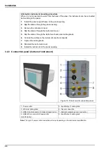
Figure 13 Panel mount connection panel
1 - Power cable
5 - Input/Output 1 cable gland
2 - Ethernet cable gland
6 - Sensor connection
3 - USB-A host connector for mass storage device
7 - External pressure sensor connection
4 - USB-B 4 pin connector (reserved for
manufacturing)
8 - Input/Output 2 cable gland
Содержание ORBISPHERE K1200
Страница 1: ...DOC024 52 93022 ORBISPHERE Model K1200 Sensor and Model 510 Analyzer USER MANUAL 11 2017 Edition 12...
Страница 5: ...4 Table of Contents...
Страница 13: ...12 General Information...
Страница 39: ...38 Installation...
Страница 45: ...44 User Interface...
Страница 46: ...45 Section 5 View Menu Figure 34 View menu...
Страница 49: ...48 View Menu...
Страница 59: ...58 Calibration Menu...
Страница 60: ...59 Section 8 Inputs Outputs Menu Figure 40 Inputs Outputs menu...
Страница 62: ...61 Inputs Outputs Menu 8 4 Analog outputs Figure 41 Analog outputs menu...
Страница 69: ...68 Inputs Outputs Menu...
Страница 86: ...85 Section 11 Products Menu Figure 44 Products menu...
Страница 89: ...88 Global Configuration Menu...
Страница 90: ...89 Section 13 Services Menu Figure 46 Services menu Part 1...
Страница 91: ...90 Services Menu Figure 47 Services menu Part 2...
Страница 99: ...98 Maintenance and Troubleshooting...


