36
UTD.123.2019-10.00_EN
7.8 - Hollow low speed shaft mounting
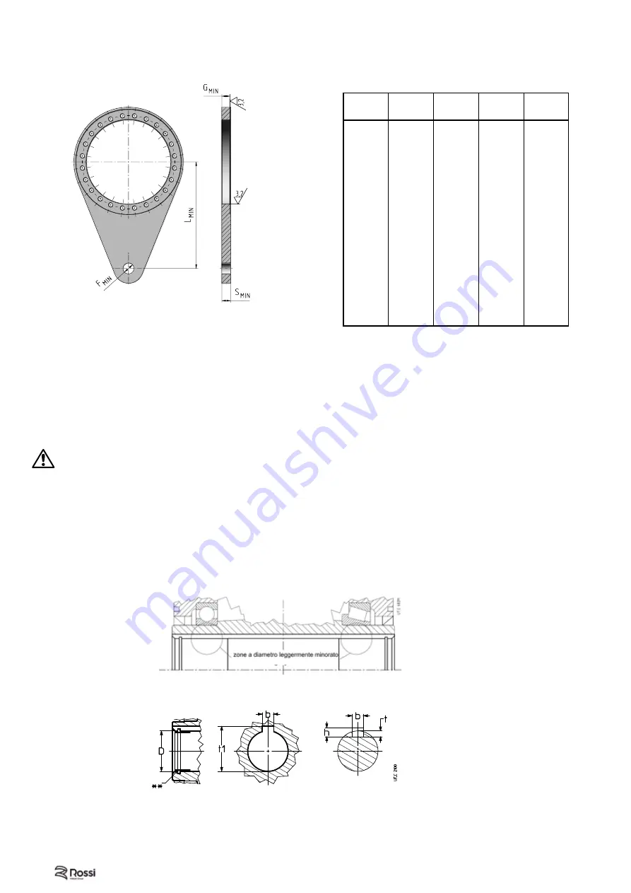
For machine shaft ends onto which the hollow shafts of gear reducers are to be keyed, h6, j6, and k6
tolerances are recommended, according to requirements (duty type, overloads, etc.).
Important!
The shoulder diameter of the driven machine shaft end abutting with the gear reducer must be
at least 1,18
÷
1,25 times the internal diameter of the hollow shaft. For other data on machine shaft end, in
case of standard hollow low speed shaft, stepped shaft, with locking rings or bushing, with shrink disc see
Rossi technical catalogs.
When assembling a hollow low speed shaft gear reducer verify that the hollow shaft is in line with the
machine shaft end.
Attention!
For
vertical ceiling-type
mounting and only for gear reducers equipped with locking rings
or bush, gear reducer support is due only to friction, for this reason it is advisable to provide it with a
fastening system.
Warning!
Even if hollow low speed shaft are completely machined in H7 tolerance, a check through bott
could reveal two zones with
slightly lowered
diameter (see fig. 5.6.1): this lowering is intentional and not
affecting the
keying quality
– which is
improved
in terms of
duration
and
precision
– and is nt hindering
the mounting of machine shaft end executed as shown in fig. 7.8.1.
Warning!
When
mounting
the gear reducer on the machine shaft end, D diameter (**, see fig. 7.8.2) at
hollow shaft engagement (standard, stepped shaft, with shrink disc) it is slightly oversized compared with
the rated dimensions: However this won't affect the connection reliability.
gear reducer
Machine shaft
Fig. 7.8.2
Fig. 7.8.1
System with
torque arm EP series
Symmetrical torque arm is provided as standard option (,TA - up to size 085A); if you need a one sided
torque arm, it must comply with the dimensions shown below.
Size
L
min
G
min
S
min
F
min
[mm]
[mm]
[mm]
[mm]
001A
325
10
15
20
002A
325
10
15
20
003A
375
13
15
20
004A
375
13
15
20
006A
375
13
15
20
009A
450
18
20
30
012A
450
18
20
30
015A
450
18
20
30
018A
550
23
25
35
021A
550
23
25
35
030A
600
28
30
35
042A
700
33
35
40
060A
800
33
35
40
085A
900
38
40
45
125A
1000
40
45
50
180A
1100
45
50
60
250A
1250
50
55
70
355A
1400
58
65
80
500A
1550
65
70
90
710A
1700
74
80
100
Tab. 7.7.1
Содержание Rossi A Series
Страница 1: ...A E G H EP series ATEX Operating Instructions ...
Страница 7: ...7 UTD 123 2019 10 00_EN This page is intentionally left blank ...
Страница 118: ...118 UTD 123 2019 10 00_EN ...
Страница 119: ...119 UTD 123 2019 10 00_EN ...


