17
CAUTION:
•
During the installation or removal process, be careful not to touch the golden plating on the
transceiver module.
•
Before inserting a transceiver module into a port, make sure the transceiver module aligns with
the port correctly.
•
If a transceiver module has a fiber connected, remove the fiber before installing the transceiver
module.
Installing an XFP/QSFP+/SFP+/SFP/QSFP28 transceiver
module
The installation procedure is similar for XFP, QSFP+, QSFP28, SFP+, and SFP transceiver modules.
The following uses an SFP+ transceiver module for illustration.
To install an SFP+ transceiver module:
1.
Wear an ESD wrist strap and make sure it makes good skin contact and is reliably grounded.
For more information, see "
."
2.
Remove the dust plug from the target fiber port.
3.
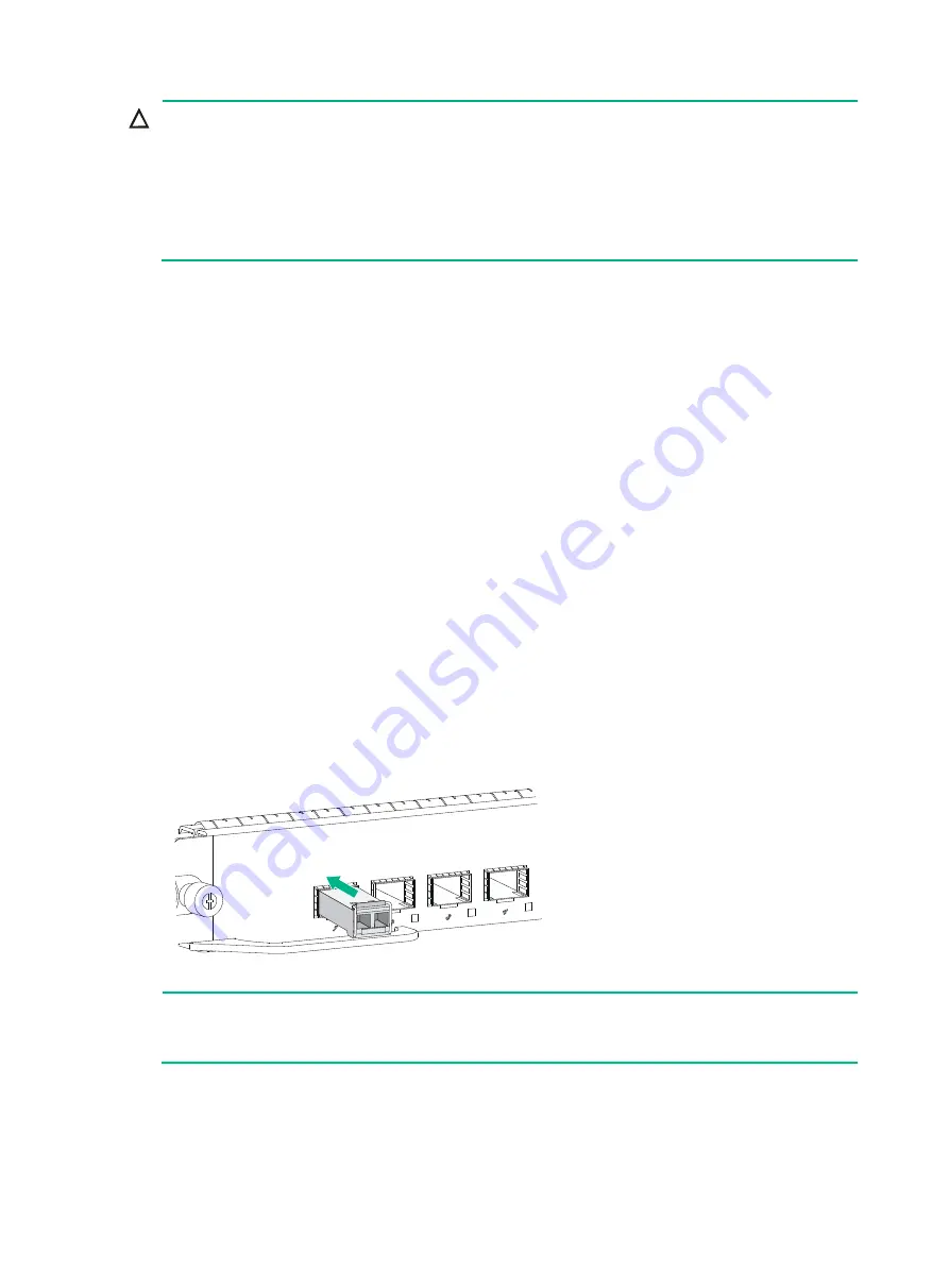
As shown in
, close the bail latch upward to catch the knob on the top of the
transceiver module. Then correctly orient the transceiver module and align it with the fiber port,
and push it gently into the port until you feel it snap into place.
Transceiver modules and fiber ports have disorientation rejection designs. If you cannot insert a
transceiver module easily into a port, the orientation might be wrong. Remove and reorient the
transceiver module.
In case of limited space, you can gently push against the front face of the transceiver module
instead of the two sides.
4.
If you are not to install an optical fiber, insert a dust plug into the transceiver module bore.
5.
Connect a fiber to the module. For the installation procedure, see "Connecting the router to the
network."
Figure 18 Installing an SFP+ transceiver module
NOTE:
The triangular pin on a transceiver module and the hole in a fiber port function together to prevent
the module from disengaging from the port.
Installing a CFP transceiver module
1.
Wear an ESD wrist strap and make sure it makes good skin contact and is reliably grounded.
For more information, see "
."
Содержание SR8800-F
Страница 49: ...6 debugging commands in H3C SR8800 F Routers Network Management and Monitoring Command Reference ...
Страница 126: ...6 Figure 4 E1 cable 1 HM96 RJ 45 ...
Страница 127: ...7 Figure 5 E1 cable 2 HM96 SMB ...
Страница 148: ...12 Figure 14 Example of a device label ...


