background image

16

C

HAPTER

 1: O

VERVIEW

H3C MSR 30-40 Router

Appearance

1

Front view

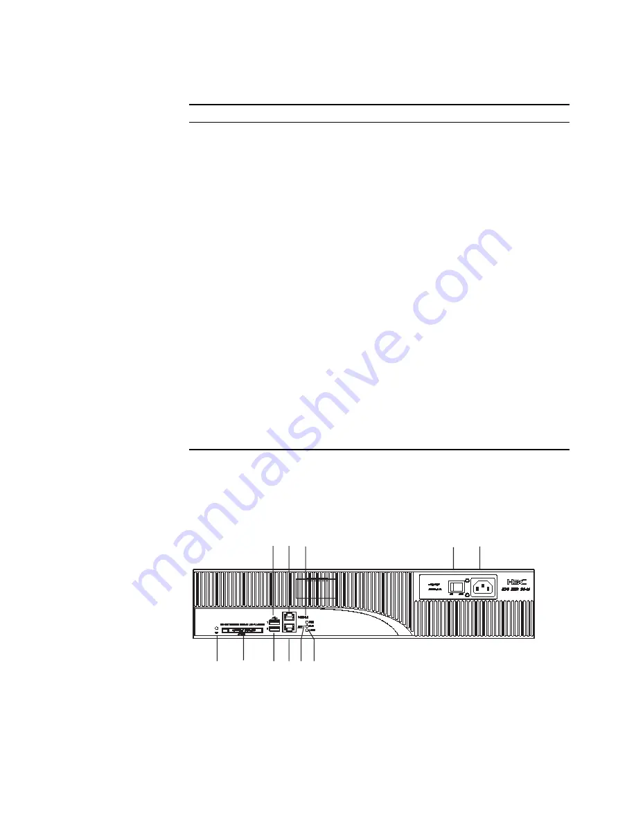
Figure 7   

Front view of H3C MSR 30-40

Table 10   

Rear panel LEDs of H3C MSR 30-20 Router

LED Description 

GE LED 

OFF means no link is present.

Steady green means a 1000 Mbps connection has been 
established.

Blinking green means data is being received or transmitted at a 
speed of 1000 Mbps.

Steady yellow means a 10/100 Mbps connection has been 
established.

Blinking yellow means data is being received and transmitted at a 
speed of 10/100 Mbps. 

ESM0 to 1 

OFF means no ESM is in the ESM slot.

Steady green means an ESM is in the ESM slot and operates 
normally.

Blinking green means the ESM is processing data.

Steady yellow means an ESM is in the ESM slot but does not 
operate normally. 

VCPM 

OFF means no VCPM is in the slot.

Steady green means a VCPM is in the slot and operates normally.

Steady yellow means a VCPM is in the slot but does not operate 
normally. 

VPM0 to 1 

OFF means no VPM is in the VPMx slot.

Steady green means a VPM is in the VPM slot and operates 
normally.

Steady yellow means a VPM is in the VPM slot but does not 
operate normally.

(1) Power LED (PWR) 

(2) System LED (SYS) 

(3) USB LED 

(4) Console port (CONSOLE) 

(5) Auxiliary port (AUX) 

(6) USB interface 0 

(7) USB interface 1 

(8) CF card LED 

(9) CF card 

(10) Power receptacle 

(11) Power switch 

(2) (3)

(10)

(8)

(9)

(6) (5)

(7) (4) (1)

(11)

Содержание MSR 30-16

Страница 1: ...H3C MSR 30 Series Routers Installation Manual v1 00 MSR 30 11 MSR 30 16 MSR 30 20 MSR 30 40 MSR 30 60 BOM 3104A10T www 3Com com Part Number 10016320 Rev AA August 2007...

Страница 2: ...as provided in DFAR 252 227 7015 Nov 1995 or FAR 52 227 14 June 1987 whichever is applicable You agree not to remove or deface any portion of any legend provided on any licensed program or documentat...

Страница 3: ...date user documentation and operating software for the MSR 30 Series router point your web browser to www 3Com com and select the Support and Registration link Please note that you must register your...

Страница 4: ...4 GET THE LATEST DOCUMENTATION AND SOFTWARE FOR YOUR H3C ROUTER...

Страница 5: ...5 3 INSTALLATION Installation Process 27 Installing Cabinets 28 Installing the Router 28 Installing Generic Modules 29 Connecting the PGND 30 Connecting the Power Cord 30 Connecting the Console Termin...

Страница 6: ...and Configuration File 74 Dealing with Router Password Loss 76 Backing up and Restoring BootROM 77 6 HARDWARE MAINTENANCE Preparing Tools 79 Opening Closing the Chassis Cover 79 Internal Structure of...

Страница 7: ...1 lists icon conventions that are used throughout this guide Table 2 lists text conventions that are used throughout this guide Table 1 Notice Icons Icon Notice Type Description n Information note Inf...

Страница 8: ...terface Card and Interface Module Manual Covers the pinouts function interface attributes panels and LEDs of all interface cards and modules available with the router LMR Series Routers Cable Manual D...

Страница 9: ...i function interface modules MIMs Currently the MSR 30 11 can adopt AC only the MSR 30 16 can adopt AC and PoE and the MSR 30 20 30 40 and 30 60 can adopt AC DC and PoE Except the MSR 30 11 and the AC...

Страница 10: ...30 20 MSR 30 40 MSR 30 60 External cards SIC 2 4 4 4 4 MIM 1 1 2 4 6 XMIM 1 0 0 0 0 Internal cards ESM 1 2 2 2 2 VCPM 0 1 1 1 1 VPM 0 2 2 3 3 Table 3 Processor and memory of the H3C MSR 30 series rout...

Страница 11: ...DC PoE input Not supported Rated voltage range 100 VAC to 240 VAC 50 Hz or 60 Hz Rated voltage range 100 VAC to 240 VAC 50 Hz or 60 Hz Rated voltage range 100 VAC to 240 VAC 50 Hz or 60 Hz Rated volta...

Страница 12: ...inking The system runs normally ON or OFF The system runs abnormally ESM OFF No ESM is in position Solid green An ESM is in position and works normally Blinking green The ESM is processing data Solid...

Страница 13: ...mally USB0 OFF means the USB interface has not been connected to a host Steady green means the USB interface is connected to a host and the host can be removed Blinking green means data is being trans...

Страница 14: ...y VCPM OFF means VCPM is not in the slot Steady green means a VCPM is in the slot and operates normally Steady yellow means a VCPM is in the slot but does not operate normally VPM0 to 1 OFF means no V...

Страница 15: ...he system is operating normally Steady ON or steady OFF means the system does not operate normally USB0 OFF means the USB interface has not been connected to a host Steady green means the USB interfac...

Страница 16: ...dy green means an ESM is in the ESM slot and operates normally Blinking green means the ESM is processing data Steady yellow means an ESM is in the ESM slot but does not operate normally VCPM OFF mean...

Страница 17: ...40 router LED Description PWR Power LED ON means the system provides power for cards normally OFF means the system does not supply power for cards SYS Hardware system operation LED Blinking means the...

Страница 18: ...of 10 100 Mbps SFP0 to 1 OFF means no SFP connection is established Steady green means SFP connection has been established Blinking green means SFP is receiving or transmitting data Steady yellow mea...

Страница 19: ...D PWR 2 System LED SYS 3 USB LED 4 Console port CON 5 Auxiliary port AUX 6 USB interface 0 7 USB interface 1 8 CF card LED 9 CF card 10 Power receptacle 11 Power switch 3 2 1 4 5 6 7 10 8 9 11 1 VCPM...

Страница 20: ...ost and the host cannot be removed now CF CF card LED Steady green means the CF card is in the slot and can be identified by the router Blinking green means the CF card is being accessed and cannot be...

Страница 21: ...W 1FEA 1GEC 1ADSL 1ADSL I can be installed only in slot 2 SIC 2BS 2BU 2BSV is not supported SIC 1BS 1BU 1BSV 1EPRI 1E1 F 1TPRI 1T1 F can be installed only in slot 1 For the MSR 30 16 SIC DSIC cards ar...

Страница 22: ...odule ESM SNDE ESM module supports IPSec and by using hardware encryption expedites IP packet encryption The use of hardware encryption decryption and hashing operation allows the router to encrypt pa...

Страница 23: ...of the insulating materials and shorten the service life of the router The requirements on the temperature and humidity for H3C MSR 30 Series are shown in the following table Requirements on Cleannes...

Страница 24: ...ard and avoid contacting the devices on it Requirements on Electromagnetic Environments The interference sources no matter where they come from affect the routers with capacitance coupling inductance...

Страница 25: ...tes that this operation is incorrect and may seriously damage the router or endanger the operator Please follow the correct operation procedures for sake of safety c Caution It indicates that during t...

Страница 26: ...wer cord Console cable Optional cables Meters and equipment Hub or LAN switch Console terminal it could be a PC Equipment related to the selected modules Multimeter c CAUTION H3C MSR 30 Series Routers...

Страница 27: ...ion Connect to the WAN Connect to the Ethernet Install multifunctional interface modules End Poweron Poweron Verify installation Connect to the console terminal Connect thepow er cord Connect PGND Sta...

Страница 28: ...r in a Rack Dimensions The MSR 30 Series Routers are designed to fit standard 19 inch racks The following table describes their dimensions Installation process Step 1 Check the grounding and stability...

Страница 29: ...Modules Installing generic modules includes installing the memory ESM cards and FICs For more information about the memory and ESM cards and their installation refer to Hardware Maintenance on page 79...

Страница 30: ...uter which is marked with grounding label is located near the AC power socket and its switch on the rear panel of the chassis as shown in the following figure Figure 14 Grounding terminal of the route...

Страница 31: ...re that the power supply of the building is well grounded Connecting the AC input power cord Step 1 Make sure that the PGND is securely connected to the earth ground Step 2 Insert one end of the power...

Страница 32: ...l Then connect the other end of the power cord with a BGND connector and a 48 VDC connector to a 48 VDC power supply w WARNING When connecting the DC power cord notice the labels on the power cord to...

Страница 33: ...cting the Power Cord 33 Connecting the RPS Power Cord RPS power Figure 18 RPS power Connecting the RPS power cord Figure 19 Prize the protective barrier of RPS Figure 20 Take the protective barrier of...

Страница 34: ...cable Console cable is an eight wire shielded cable At one end of the cable is a crimped RJ 45 connector to the console port on the router at the other end of the cable is a DB 9 female connector to...

Страница 35: ...SR 30 16 provide two fixed FE interfaces the MSR 30 20 provides two fixed GE interfaces and the MSR 30 40 30 60 provides two fixed Combo interface In addition H3C MSR 30 Series Routers provide SIC and...

Страница 36: ...s in different sequences The cable connects the same category of devices such as PC to PC or PC to router You can make crossover cables yourself as needed n In making network cables shielded cables ar...

Страница 37: ...ser danger Invisible laser radiation may be emitted from the fiber optic ports which are connected with lasers To protect your eyes against radiation harm never stare into an open fiber optic port Fol...

Страница 38: ...configuration or dial backup you need to connect the local modem to the remote modem through PSTN and then to the remote device For the configuration procedures refer to H3C MSR 20 30 50 Series Router...

Страница 39: ...and Removal 39 Installing the Slide Rails Figure 26 Install the slide rails into the MSR 30 11 Figure 27 Router view after the slide rail is replaced Removing the Slide Rails Figure 28 Loosen the scre...

Страница 40: ...STALLATION Slide Rail Installation on MSR 30 16 30 20 and Removal Slide Rails SIC slide rail Figure 30 SIC slide rail Installing the Slide Figure 31 Insert the slide rail into the router Figure 32 Fix...

Страница 41: ...nstalling the Slide Rail Figure 33 Loosen the screws Figure 34 Router view after the slide rail is drawn out Slide Rail Installation on MSR 30 40 30 60 and Removal Slide Rails SIC slide rail Figure 35...

Страница 42: ...CHAPTER 3 INSTALLATION Figure 37 MIM slide rail right Installing the Slide Rail Figure 38 Install the SIC slide rail Figure 39 Install the MIM slide rail left Figure 40 Install the MIM slide rail rig...

Страница 43: ...ly When installing a DMIM it is recommended that you fasten the release screw first and then install the DMIM on the other side of the rail Uninstalling the Slide Rail Figure 41 Uninstall the SIC slid...

Страница 44: ...rrectly connected Whether the router is correctly connected to other devices such as the console terminal c CAUTION The check after installation is very important The stability grounding of the router...

Страница 45: ...guration environment RJ 45 connector of the console cable needs to be connected to the console port on the router and DB 9 connector to the serial interface of a PC as shown in the following figure Fi...

Страница 46: ...ce connected by the console cable Figure 44 Local configuration connection interface 2 Setting terminal parameters As shown in the following table in the properties dialog box of the serial interface...

Страница 47: ...HyperTerminal properties Select FilePropertiesSettings in the HyperTerminal to enter the properties setting window as shown in the following figure Select the terminal emulation type to be VT100 or a...

Страница 48: ...her the PC or terminal for configuration is open and whether the settings are done Whether the CF card is loosed w WARNING Before powering on the router the user should be aware where the switch of th...

Страница 49: ...er the decompression process of the extended BootROM segment n Enter Ctrl D within 3 seconds after the Press CTRL D to stop auto boot appears the system can enter basic BootROM segment menu otherwise...

Страница 50: ...started Press Enter and the screen will display H3C This prompt indicates that the router has entered the user view and now the router can be configured Configuration Fundamentals In general the confi...

Страница 51: ...to directly log on and manage other routers Users can enter anytime to get online help Provides network diagnostic tools such as Tracert and Ping to quickly diagnose the availability of the network Pr...

Страница 52: ...ement on the MSR 30 20 Figure 50 Slot arrangement on the MSR 30 40 1 Slot 0 2 Slot 1 3 Slot 2 4 Slot 3 1 Slot 0 2 Slot 1 3 Slot 2 4 Slot 3 5 Slot 4 6 Slot 5 1 Slot 0 2 Slot 1 3 Slot 2 4 Slot 3 5 Slot...

Страница 53: ...le share the same slot number X For every interface Y starts from 0 and indicates the interface sequence on the interface module from left to right If you install a MIM 1FE and an MIM 2FE respectively...

Страница 54: ...54 CHAPTER 4 STARTUP AND CONFIGURATION...

Страница 55: ...not type N You can modify the file name of an application file in CF card using the command after it boots You cannot modify the file type of a type S application image file but you can modify the fi...

Страница 56: ...ing commands after the application program boots You can store them in Flash memory but only one for each For example if an M B file exists it is impossible to have another M or B file If you change t...

Страница 57: ...ng XModem protocol through serial port 2 Upgrade application program from TFTP FTP server through Ethernet interface in BootROM 3 Upload download application program and configuration file from TFTP F...

Страница 58: ...em start booting Version 2 11 Press CTRL D to stop auto boot Booting Normal Extend BootRom Decompressing done Ensure the baudrate is set to 9600bps Starting at 0xa00000 H3C MSR30 20 BOOTROM Version 2...

Страница 59: ...password You have three chances to provide the correct BootROM password the initial setting is void If you fail to do that you need to reboot the system After you enter the correct password the conso...

Страница 60: ...on File 4 File Control File control submenu Refer to File control submenu on page 61 for details 5 Modify Bootrom Password Modify BootROM password 6 Ignore System Configuration Ignore system configura...

Страница 61: ...operation submenu Enter 7 under the main BootROM menu to enter the BootROM operation menu BOOT ROM OPERATION Note the operating device is CF Card Table 28 Enter Ethernet interface submenu Menu item D...

Страница 62: ...r 2 in the main BootROM menu to enter the serial submenu Then enter 5 and the system prompts to change serial baud rate BAUDRATE SET Note Change The HyperTerminal s Baudrate Accordingly Press Enter to...

Страница 63: ...can not communicate with each other Change the baud rate of your terminal to the same as that for software download Perform the following operation Figure 53 Disconnect terminal Click File Properties...

Страница 64: ...submenu under which all BootROM operations are completed Refer to BootROM operation submenu on page 61 for detailed descriptions For example when you upgrade full BootROM First change serial baud rate...

Страница 65: ...yperTerminal to 9600 bps the default after upgrading the BootROM so as to ensure normal display on the console screen after system boot or reboot UpgradingApplication Program Through Serial Port Upgra...

Страница 66: ...e download file name shall be consistent with the real file name and you are asked to designate download path Or you can designate download path in FTP and TFTP settings inet on ethernet e 192 168 80...

Страница 67: ...r protocol in the TCP IP suit It mainly transfers files among remote hosts Carried over TCP it provides reliable and connection oriented data transfer service but does not provide access authorization...

Страница 68: ...8 Clear Super Password 9 Device Operation a Reboot Enter your choice 1 a 4 The system reboots Enter 4 when it prompts the above information File CONTROL Note the operating device is CF Card 1 Display...

Страница 69: ...ded here will replace the original M file directly to become the main boot program Refer to Files on page 55 for detailed descriptions of file types Maintaining Application Program and Configurations...

Страница 70: ...06 09 55 28 logfile 2 rw 909 Apr 04 2006 10 54 38 ar router cfg 3 rw 1045 Apr 04 2006 11 31 36 configbak cfg 4 rw 14323376 Mar 31 2006 17 50 22 backup bin 63340 KB total 20928 KB free File system type...

Страница 71: ...connection oriented data transfer service but does not provide access authorization and authentication mechanism The FTP service provided by the router is FTP Server that is to say the router serves...

Страница 72: ...ame configured on the router 331 Password required for guest Password Enter the password 123456 230 User logged in Successfully connected to the server Now we can use the following command to perform...

Страница 73: ...om 3CDaemon FTP Server Version 2 0 User 192 168 0 1 none guest Enter the user name configured on the router 331 User name ok need password Password Enter the corresponding password 230 User logged in...

Страница 74: ...23 2006 15 39 cf config cfg 3 160 Mar 20 2006 09 55 cf private data txt 4 14323456 Mar 25 2006 10 38 cf secure bin 5 238664 Mar 27 2006 10 50 cf logfile logfile log Set application file type Enter 2 u...

Страница 75: ...the file type Enter File Name cf router cfg Modify this file Attribute 1 Main 2 Main 3 Backup 4 Backup 5 Exit Enter your choice 1 5 You can set the operation file to the types of M Cancel M B and Can...

Страница 76: ...set authentication password simple 123456 This indicates that the password authentication is adopted at the Console port and the password is set to 123456 and stored in plain text n After rebooting th...

Страница 77: ...first reboot of the router the Super Password restores after the second reboot Backing up and Restoring BootROM Enter 7 under the main BootROM menu to enter the BootROM operation submenu Refer to Boot...

Страница 78: ...78 CHAPTER 5 SOFTWARE MAINTENANCE...

Страница 79: ...Power off the router and remove the power cord Step 2 Remove all cables of interface modules on the back panel keep the ground cable connected Step 3 Put the router on level ground and have the back...

Страница 80: ...Figure 63 Rotate the screwdriver Figure 64 Pull out the chassis cover until it is separated from the chassis Figure 65 Remove and fasten the captive screws of the MSR 30 40 30 60 Figure 66 Open the ch...

Страница 81: ...pen the chassis yourself but with permission of your sales agent and must operate following the related rules The company is not liable for any damage or consequence resulted from users operation with...

Страница 82: ...MSR 30 11 internal structure n The current version of the MSR 30 11 does not support any CF card but the later versions will do Therefore a CF card slot is reserved on the MSR 30 11 1 Slide rails 2 M...

Страница 83: ...ucture of the Router 83 Figure 68 MSR 30 16 internal structure 1 Power module 2 CF card slot 3 VPM 4 ESM slot 1 5 VCPM slot 6 MIM slot 7 SIC card slot 8 Fan 9 Memory module slot 10 ESM slot 0 1 5 2 3...

Страница 84: ...structure of the MSR 30 40 30 60 Before the power module is removed 1 Power module 2 VPM 3 CF card slot 4 VCPM slot 5 ESM slot 1 6 MIM card slot 7 SIC slot 8 Fan module 9 Memory module slot 10 ESM slo...

Страница 85: ...module of the MSR 30 11 is irremovable This section illustrates how to remove the power module from the MSR 30 40 30 60 For the other modules only step 1 applies 1 Remove the power bracket from the ro...

Страница 86: ...Figure 72 Remove the screws from the bracket Draw out the power bracket and remove the power cord from the main board Figure 73 Remove the power bracket and the power cord 2 Remove the power module f...

Страница 87: ...t Separate the power module from the bracket Figure 75 Draw out the power module and separate it from the bracket n The installation procedure is just opposite to the removal procedure Installing Remo...

Страница 88: ...emove the CF card following these steps Step 1 Check the CF card LED to make sure it is not blinking and then proceed Step 2 Press the spring button to release the internal spring clip making the card...

Страница 89: ...memory module is damaged c CAUTION Hold the memory module by its edge and avoid touching the components on its surface An improper operation might result in damage It is normal that you feel hard when...

Страница 90: ...module on from the MSR 30 16 Follow the steps below to install a memory module Step 1 Make sure all power interfaces are shut down Step 2 Align the connecting fingers of the memory module with the sl...

Страница 91: ...memory module outwards horizontally until it separates from the ejector clips and forms an angle of 45 degrees to the main board Step 3 Remove the memory module Figure 85 Remove a memory module Instal...

Страница 92: ...re 86 Install a memory module Follow the steps below to remove a memory module Step 1 Make sure all power interfaces are shut down Step 2 Press the ejector clips on the two sides of the memory module...

Страница 93: ...ees to the main board Step 4 Press the top edge of the VPM module perpendicularly to the main board until the VPM snaps into the slot At this time the VPM forms a certain angle to the main board Figur...

Страница 94: ...t and press down vertically to install the card on the board Then align the screw eye with the card bracket Step 5 Fasten the card on the bracket with dedicated screws making sure the card is level an...

Страница 95: ...Configuration System If the router passes POST after powered up the console screen displays the startup banner if faults occur to the configuration system the console screen displays nothing or only i...

Страница 96: ...name main bin inet on ethernet e 192 168 0 2 host inet h 192 168 0 1 user u guest ftp password pw 123456 flags f 0x80 Loading Done 0 bytes downloaded Something wrong with the file 2 Solution Fault oc...

Страница 97: ...an incorrect application image file is downloaded Download the correct application image file n The bar code labels on the chassis and the FICs contain information about production and servicing Befor...

Отзывы: