


5-1
5
Connecting cables
Connecting cables to Ethernet copper ports
Cables for connecting Ethernet copper ports
Typically, Ethernet copper ports use twisted pair cables for communication. 10/100 Mbps Ethernet
uses category-5 twisted pair cables, while 1000 Mbps Ethernet uses category-5 enhanced or
category-6 twisted pair cables. Twisted pair cables include straight-through cables and crossover
cables.
•
Category-5 cables provide a transmission frequency of 100 MHz for voice and data
transmission; they are mainly used in 100BASE-T and 10BASE-T networks. Category-5 cables
are the most commonly used Ethernet cables, which can also be used to transmit 1000 Mbps
Ethernet data.
•
Category-5 enhanced cables feature low attenuation and crosstalk, providing higher
attenuation to crosstalk ratio (ACR), less delay error and higher performance than category-5
cables. Category-5 enhanced cables are mainly used in 1000 Mbps Ethernet networks.
•
Category-6 cables provide a transmission frequency of 1 MHz to 250 MHz, and improve the
performance on crosstalk and return loss. A fine better return loss performance is extremely
important for new-generation full-duplex high-speed networks. Category-6 cables have
sufficient power sum ACR (PS-ACR) when working at 200 MHz. They provide a bandwidth two
times than that of category-5 enhanced cables, featuring a higher transmission performance.
Therefore, category-6 cables are suitable for applications requiring a transmission speed of
more than 1 Gbps.
The 10/100 Mbps Ethernet uses two pairs of cables, orange/white, orange, green/white and green
cables, to transmit and receive data, while the 1000 Mbps Ethernet uses four pairs of cables to
transmit and receive data.
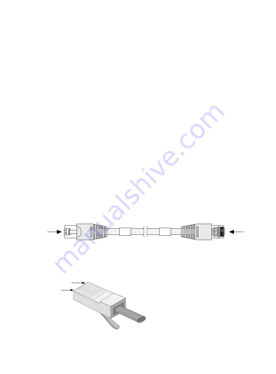
Figure5-1 Ethernet cable
RJ-45 connector
An Ethernet twisted pair cable connects network devices by using the RJ-45 connectors at the two
ends.
shows the pinouts of an RJ-45 connector.
Figure5-2 RJ-45 connector pinout diagram
B
A
1
8
1
8
PIN #8
PIN #1
Содержание CR19000-20
Страница 11: ...1 5 Figure1 1 Chassis dimensions...
Страница 39: ...2 9 Figure2 7 Securing the router to the rack...
Страница 61: ...4 2 Figure4 1 Slot arrangement...
Страница 84: ...6 5 Figure6 4 Installing an air filter...
Страница 97: ...8 9 Figure8 9 Removing a fan tray...
Страница 103: ...8 15 Figure8 18 Securing the new power tray...
Страница 131: ...11 7 Figure11 8 Routing AC power cords...
Страница 132: ...11 8 Figure11 9 Routing DC power cords...
Страница 139: ...12 6 Figure12 3 Packing component positions...


