background image

10

SMARTFEED M-4

EN

ELECTRO-MAGNETIC EMISSIONS

The electric current flowing through any conductor causes electrical and magnetic fields (EMF). The welding current generates an 

EMF around the welding circuit and the welding equipment.

The EMF electromagnetic fields can interfere with certain medical implants, such as pacemakers. Protective measures must be taken for people having 

medical implants. For example, by restricting access to passers-by or conducting an individual risk evaluation for the welders.

All welders must use the following procedures to minimize exposure to electromagnetic fields from the welding circuit:

• position the welding cables together - fix them with a clamp, if possible;

• position yourself (torso and head) as far away from the welding circuit as possible;

• never wrap the welding cables around the body;

• do not position the body between the welding cables. Hold both welding cables on the same side of your body;

• connect the earth clamp as close as possible to the area being welded;

• do not work too close to, do not lean and do not sit on the welding machine

• do not weld when transporting the welding machine or its wire feeder.

People wearing pacemakers are advised to consult their doctor before using this device.

Exposure to electromagnetic fields during welding can have other health effects that are not yet known.

EQUIPMENT INSTALLATION

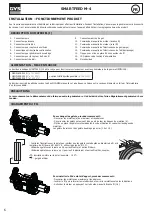
• Put the wire feeder on a floor with a maximum incline of 10°.

- Provide sufficient area to ventilate the feeder and access the controls..

• This equipment must be used and stored in a place protected from dust, acid, gas or any other corrosive substance.

- The dispenser must be protected from driving rain and not exposed to sunlight.

• The machine protection level is IP21, which means:

- Protection against acess to dangerous parts from solid bodies of a ≥12.5mm diameter and,

- Protection against vertically falling drops.

This material is designed for indoor use.

Power cables, extension leads and welding cables must be fully uncoiled to prevent overheating.

GYS  does  not  incur  any  responsibility  regarding  damages  to  both  objects  and  persons  that  result  from  an  incorrect  and/or 

dangerous use of the machine.

MAINTENANCE / RECOMMENDATIONS

• Maintenance should only be carried out by a qualified person. A yearly maintenance is recommended.

• Ensure the wire feeder is disconnected from the welding machine, and wait for two minutes before carrying out maintenance 

work.

• Remove regularly the casing and any excess of dust. Take this opportunity to have the electrical connections checked by a qualified person, using 

an insulated tool.

• Regularly check the condition of the connection cable between the wire feeder and the machine. If found damaged, the interconnection cable must 

be replaced.

• Warning !  If the welding machine is transported/handled by another solution than the one recommended by the manufacturer; the wire feeder 

casing must be insulated from the transporting/handling solution.

Rules to follow :

• The wire feeder must be switched on with all access panels closed.

Stray welding currents can damage earth connections, damage electrical equipment and cause overheating of components which 

could result in fire.

- All welding connections must be firmly secured, check regularly !

-  Make sure that the metal part fixation is strong and without any electrical problems !

- Attach or hang all the electrically conductive elements, such as the trolley or lifting systems in order to insulate them !  

- Do not place any non-insulated electrical equipment such as drills on top of the welding machine or its trolley without insulating them!

- Always place welding torches or electrodes holders on an insulated surface when they’re not in use!

Содержание SMARTFEED M-4

Страница 1: ...8 SMARTFEED M 4 D vidoir robotique Robotic wire feeder Drahtvorschubkoffer Draadaanvoersysteem Devanadera rob tico Trainafilo robotizzata www gys fr EN 2 8 12 33 38 DE 2 13 17 33 38 ES 2 18 22 33 38 N...

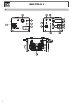
Страница 2: ...2 SMARTFEED M 4 I 1 2 3 5 8 9 6 10 11 12 13 14 16 15 4 7...

Страница 3: ...ons de nettoyage Les lentilles de contact sont particuli rement proscrites Il est parfois n cessaire de d limiter les zones par des rideaux ignifug s pour prot ger la zone de soudage des rayons de l a...

Страница 4: ...inces c bles lectrodes car celles ci sont branch es au circuit de soudage Avant d ouvrir la source de courant de soudage il faut la d connecter du r seau et attendre 2 minutes afin que l ensemble des...

Страница 5: ...otection contre les chutes verticales de gouttes d eau Ce mat riel est con u pour une utilisation l int rieur Les c bles d alimentation de rallonge et de soudage doivent tre totalement d roul s afin d...

Страница 6: ...ption IHM d port e possible ref 062122 Ce d vidoir pourra tre utilis avec des torches MIG MAG manuelles et robotiques La liaison entre ces deux l ments se fait par l interm diaire d un faisceau d di P...

Страница 7: ...SEC 24V DC 1 24VDC 2 5 DO1 DO4 NO Photocoupleur isolation 500 VDC 6 9 DI1 DI4 NO 10 Masse 0V ON Voltage Vmin Vmax 20V 30 V 15VDC 28VDC OFF Voltage Vmin Vmax 0VDC 5 VDC Input imp dance 800 KOhm Courant...

Страница 8: ...y Wear protective gloves which guarantee electrical and thermal insulation Use sufficient welding protective gear for the whole body hood gloves jacket trousers varies depending on the application ope...

Страница 9: ...size An electric shock could cause serious injuries or potentially even deadly accidents Do not touch any live part of the machine inside or outside when it is plugged in Torches earth cable cables e...

Страница 10: ...means Protection against acess to dangerous parts from solid bodies of a 12 5mm diameter and Protection against vertically falling drops This material is designed for indoor use Power cables extension...

Страница 11: ...ith manual and robotic MIG MAG torches The connection between these two elements is made through a dedicated beam PRECAUTIONS Make sure the welding generator is switched off when connecting or disconn...

Страница 12: ...ts Output Input Insulation type Dry contact 24V DC 1 24VDC 2 5 DO1 DO4 NO Insulated 500 VDC Photocoupler 6 9 DI1 DI4 NO 10 Ground 0V ON Voltage Vmin Vmax 20V to 30 V 15VDC 28VDC OFF Voltage Vmin Vmax...

Страница 13: ...zu schweren Augensch den und Hautverbrennungen f hren Die Haut muss durch geeignete trockene Schutzbekleidung Schwei erhandschuhe Ledersch rze Sicherheitsschuhe gesch tzt werden Tragen Sie elektrisch...

Страница 14: ...arken Temperaturschwankungen z B sehr tiefen Temperaturen Positionieren Sie die Gasflaschen stets mit ausreichendem Abstand zu Schwei und Schleifarbeiten und zu jeder Hitze Funken und Flammenquelle so...

Страница 15: ...tvorschubkoffer zu bel ften und Zugang zu den Bedienelementen zu erhalten Verwenden Sie das Ger t nicht in einer elektromagnetisch sensiblen Umgebung oder in Anwesenheit von Metallst uben Sch tzen Sie...

Страница 16: ...tvorschubkoffer kann mit manuellen und robotergesteuerten MIG MAG Brennern verwendet werden Die Verbindung zwischen den Ger ten erfolgt mit einem spezifischen Kabel SICHERHEITSHINWEISE Das Zwischensch...

Страница 17: ...olierung 500 V DC 6 9 DI1 DI4 NO 10 Masse 0V ON Spannung Vmin Vmax 20V bis 30 V 15VDC 28VDC OFF Spannung Vmin Vmax 0VDC 5 VDC Inputimpedanz 800 KOhm Nennstromst rke bei 24 V Max 2A 10 mA MIT BEWEGLICH...

Страница 18: ...t jase los ojos durante operaciones de limpieza Las lentillas de contacto est n particularmente prohibidas A veces es necesario delimitar las zonas mediante cortinas ign fugas para proteger la zona de...

Страница 19: ...nzas cables electrodos ya que est n conectadas al circuito de soldadura Antes de abrir el aparato es necesario desconectarlo de la red el ctrica y esperar dos minutos para que el conjunto de los conde...

Страница 20: ...o para su uso en interiores Los cables de alimentaci n de prolongaci n y de soldadura deben estar completamente desenrollados para evitar cualquier sobrecalentamiento El fabricante GYS no asume ningun...

Страница 21: ...4497 NEOPULSE 320 C ref 062474 opci n IHM remota posible ref 062122 Esta devanadera puede ser usada con antorchas MIG MAG manuales y rob ticas La conexi n entre estos dos elementos se hace por medio d...

Страница 22: ...da Entrada Tipo de aislamiento Contacto SEC 24V DC 1 24VDC 2 5 DO1 DO4 NO Fotoacoplador aislamiento de 500 VDC 6 9 DI1 DI4 NO 10 Masa 0V ON Voltage Vmin Vmax 20V a 30 V 15VDC 28VDC OFF Voltage Vmin Vm...

Страница 23: ...hoonmaakwerkzaamheden Het dragen van contactlenzen is uitdrukkelijk verboden Soms is het nodig om het lasgebied met brandwerende schermen af te schermen tegen stralingen projectie en wegspattende gloe...

Страница 24: ...en totdat alle condensatoren ontladen zijn Raak nooit tegelijkertijd de toorts of de elektrodehouder en de massa klem aan Zorg ervoor dat de kabels en toortsen vervangen worden door gekwalificeerd en...

Страница 25: ...afnemen en met een blazer stofvrij maken Maak van de gelegenheid gebruik om met ge soleerd gereedschap ook de elektrische verbindingen te laten controleren Controleer regelmatig de staat van de verbin...

Страница 26: ...Draai de wieltjes a maximaal los en laat deze zakken Draai de rollen los door de borgringen een kwart te draaien b Plaats de door u uitgekozen rollen en draai de borgringen weer vast De meegeleverde r...

Страница 27: ...isolatie Contact SEC 24V DC 1 24VDC 2 5 DO1 DO4 NO Opto coupler isolatie 500 VDC 6 9 DI1 DI4 NO 10 Massa 0V ON Voltage Vmin Vmax 20V tot 30 V 15VDC 28VDC OFF Voltage Vmin Vmax 0VDC 5 VDC Input impeda...

Страница 28: ...occhi durante le operazioni di pulizia Le lenti a contatto sono particolarmente sconsigliate Potrebbe essere necessario limitare le aree con delle tende ignifughe per proteggere la zona di saldatura...

Страница 29: ...e 2 min affinch l insieme dei condensatori sia scarico Non toccare nello stesso momento la torcia e il morsetto di massa Controllare e provvedere a far cambiare i cavi gli elettrodi o i bracci da pers...

Страница 30: ...rofittare per far verificare la tenuta dei collegamenti elettrici con un utensile isolato Cogliere l occasione per far verificare lo stato delle connessioni elettriche con un utensile isolato Controll...

Страница 31: ...rle Sbloccare i rulli facendo un quarto di giro sulle barre che li mantengono b Posizionare i rulli motore adatti al vostro utilizzo e bloccare le barre di mantenimento I rulli forniti sono dei rulli...

Страница 32: ...istiche tecniche delle entrate e uscite Uscita Entrata Tipo isolazione Contatto SEC 24V DC 1 24VDC 2 5 DO1 DO4 NO Fotocopiatrice isolazione 500 VDC 6 9 DI1 DI4 NO 10 Massa 0V ON Voltaggio Vmin Vmax 20...

Страница 33: ...schluss der Steuerkabel Tarjeta de adaptacion haz de mando Kaart aanpassen besturingskabel Scheda adattamento fasciocavi di comando 97749C 8 lectrovanne gaz Solenoid gas valve Magnetventil Gas Electro...

Страница 34: ...SCH MA LECTRIQUE CIRCUIT DIAGRAM STROMLAUFPLAN ESQUEMA EL CTRICO ELEKTRISCH SCHEMA SCHEMA ELETTRICO M A0057 71538 55304 2 2 51403 51403 4 4 51403 51403 52013 8 6 97749C M 51018 4 4 2 2 3 3 55303 5530...

Страница 35: ...10 min Norma EN60974 1 40 10 EN60974 1 60 500 A 100 460 A Pression maximale de gaz Pmax Maximum gas pressure Pmax Maximaler Gasdruck Presi n m xima de gas Pmax Maximale gasdruk Pmax 5 bar 0 5 MPa Typ...

Страница 36: ...vas europeas La declaraci n de conformidad est disponible en nuestra p gina web A Dispositivo i conforme i alle direttive europee La dichiarazione di conformit disponibile sul nostro sito internet App...

Страница 37: ...r e d air Inlet air Luftzufuhr Entrada de aire Ingang lucht Ingresso aria Purge Gaz Gas purge Gassp lung Purga de gas Zuiveren gas Epurazione Gas Purge Air Aur purge Luftsp lung Purga de aire Zuiveren...

Страница 38: ...GYS SAS 1 rue de la Croix des Landes CS 54159 53941 SAINT BERTHEVIN Cedex France...

Отзывы: