“GF” SERIES AUTOMATIC WATER CONDITIONERS
INSTALLATION
4
Installation Procedures
Please see page 3 for installation of fitting assemblies.
All installation procedures must conform to local plumbing, electrical and sanitation codes and ordinances.
A. Planning Installation
1. It is recommended that outside faucets for lawn
service be on a hard water line, ahead of the soft-
ener. This will conserve softened water, save salt
and prevent lawn damage. If this is not practical,
use the convenient integral bypass valve assembly
during irrigation flows.
2. CAUTION: The inlet water temperature MUST
NOT EXCEED 110° F.
3. DO NOT locate the softener where ambient tem-
perature drops below 40° F.
4. Allow space around the softener for ease of servic-
ing.
5. Softener drain lines must never be solidly con-
nected to the sewer line (always provide an air gap
at the END of the drain line).
6. The drain line must NOT be elevated over 5’ from
the top of the softener on well systems, and 8’ on
municipal water systems.
7. Drain line must not extend more than 20’ in length.
If longer runs are required increase the drain size
to 1”.
8. The brine tank or salt storage cabinet is a gravity drain. This drain line must be lower than the drain fitting on
the side wall of the brine tank or cabinet.
B. General Installation
1. Turn off the main water supply before making any plumbing connections to existing piping.
2. Move the softener into position, making sure it is on a clean level surface. If shims are needed you may use
those to create a level installation. DO NOT USE METAL SHIMS
3. When installing the unit, be sure to connect the inlet and outlet to the correct ports on the valve. The bypass
valve and the control valve are both marked with arrows that indicate the direction of water flow. If water lines
are reversed resin maybe forced from the water softener and into household plumbing system. Should this
occur, the plumbing system would need to be flushed.
4. Install the bypass valve assembly. The control valve is designed to accommodate minor plumbing misalign-
ments. It is not designed to support the weight of the unit.
5. Please see page 3, item 3 for assembling and soldering of fittings.
6. Install an appropriate grounding strap across the inlet and outlet piping of the water conditioning system to
ensure that a proper ground is maintained.
7. Move the brine tank into place. Making sure that the floor is clean of any debris. Sharp objects such as rocks
can cause punctures to the brine tank over a period of time. This would not be covered under Marlo’s warranty.
(DO NOT ADD SALT AT THIS TIME).
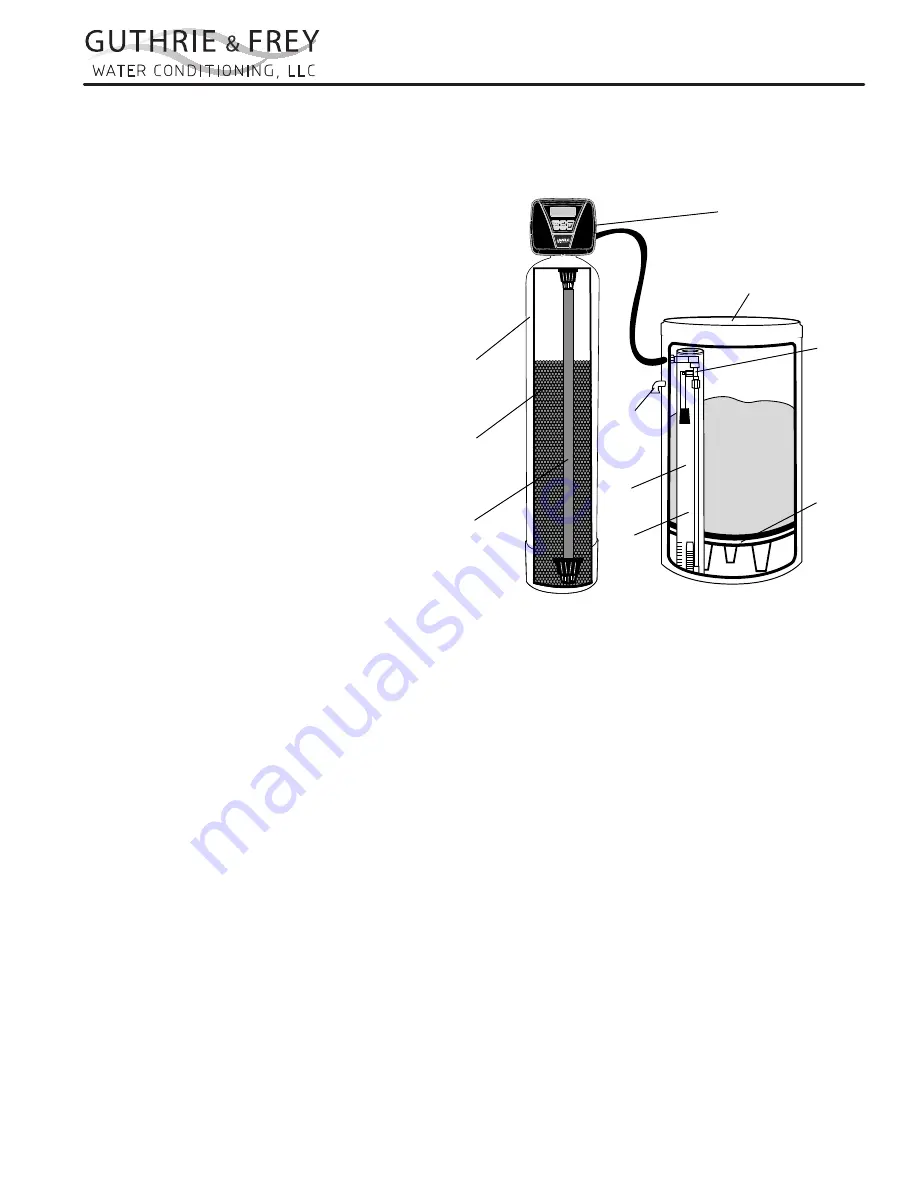
8. Connect one end of the brine line (brine line is located inside the brine tank. Marlo units come with 5’ of brine
line) to the brine elbow of the brine tank and the other end to the brine elbow on the control valve. The brine
elbow on the control valve is black in color and located on the top of the control valve. The brine elbow swivels
to allow the brine tank to be placed in a convenient position.
9. The drain line connector is located on the top of the control valve and is black in color. The water softener comes
standard with 5/8 insert and nut if installer is using a poly tube. The drain elbow is threaded, so a ¾” drain line
may also be used. NOTE: If soldering the drain line use caution so as not to cause damage to the drain elbow.
Safety
Brine
Valve
Brine Tank
Overflow
Drain
Control
Valve
Brine
Grid
Plate
Brine
Well
Air
Check
Resin
Tank
Distributor
Tube
Assembly
Ion
Exchange
Media
www.Marlo-Inc.com
Содержание GF24
Страница 27: ...GF SERIESAUTOMATIC WATER CONDITIONERS NOTES...
Страница 28: ...8 569 G F R2...


