background image

OPERATING MANUAL

ZP 3-5 V4

Project / Order:
Bill of materials:
Serial number:
Year of manufacture:

BETRIEBSANLEITUNG ZP 3-5 V4

72057594174110603_V5.0_EN-US

B1M.10xxxxxxx-xxxx
10xxxxxxx
99xxxxxxx
2018

Содержание ZP 3-5 V4

Страница 1: ...OPERATING MANUAL ZP 3 5 V4 Project Order Bill of materials Serial number Year of manufacture BETRIEBSANLE 72057594174110 B1M 10xxxxxxx xxxx 10xxxxxxx 99xxxxxxx 2018...

Страница 2: ...ay deviate from the original In the case of special models options or technical changes the scope of deliv ery may differ from the descriptions here Reprinting the instructions in whole or in part req...

Страница 3: ...Position the base plates 2 56 Anchor the base plates 2 58 General inspection 2 161 Mount motor 2 94 4 0 15 02 2018 New Feedback on instructions Chapter 9 7 2 243 Intervention report Malfunctions Trou...

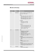
Страница 4: ...11 2016 Updated New signatures on declaration of incor poration Chapter 1 2 17 Entire manual updated 1 0 21 04 2016 Basic version Table 1 Revision history Revision history OPERATING MANUAL ZP 3 5 V4...

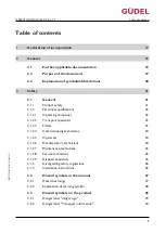
Страница 5: ...4 Commissioning technicians 24 3 1 2 5 Operators 24 3 1 2 6 Manufacturer s technicians 24 3 1 2 7 Maintenance technicians 25 3 1 2 8 Service technicians 25 3 1 2 9 Disposal specialists 25 3 1 3 Disreg...

Страница 6: ...4 2 Product designation 34 4 2 1 Type plate 34 4 2 2 Position of the type plate 35 4 3 Technical data 35 4 4 Options 36 5 Design function 37 5 1 Design 37 5 2 Function 38 6 Transport 39 6 1 Packaging...

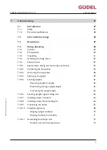
Страница 7: ...base plates 58 7 4 5 4 Setting up an upright 59 7 4 5 5 Leveling uprights 62 Measuring height of upright 62 Determining average upright height 63 Correcting the upright height 63 7 4 5 6 Securing upr...

Страница 8: ...r unit with limit stops 93 7 5 5 Installing the motor 94 7 5 5 1 Information on initial assembly 94 7 5 5 2 Prerequisites 94 7 5 5 3 Aligning the gearbox flange 95 7 5 5 4 Aligning the input shaft to...

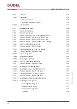
Страница 9: ...Y direction Standard 132 7 9 4 Y direction Safety brake system 133 7 10 Initial lubrication 136 7 10 1 Clean guideways and racks 136 7 10 2 Pre lubricate guideways and racks 137 7 10 3 Carrying out a...

Страница 10: ...ons 159 9 3 8 Maintenance tasks after 2 250 hours 161 9 3 8 1 General inspection 161 9 3 8 2 Replacing the battery 164 9 3 8 3 Replacing the cartridge 164 9 3 8 4 Carrying out a lubrication check 165...

Страница 11: ...oller 197 Roller positions 197 Using the mounting aid Relieving the roller 198 Replacing the roller 200 Replacing the double roller 201 Y axis 205 Z axis 209 Final tasks 210 9 3 11 6 Replacing the gui...

Страница 12: ...troduction 244 10 1 1 Safety 244 10 1 2 Personnel qualifications 245 10 2 Repairs 245 10 2 1 General prerequisites 245 10 2 2 Replacing lubricant 246 10 2 2 1 Attaching the slings Motor 246 10 2 2 2 A...

Страница 13: ...tervention report Repairs 273 10 6 Other documentation 275 10 7 Service departments 275 11 Decommissioning storage 276 11 1 Introduction 276 11 1 1 Personnel qualifications 276 11 2 Storage conditions...

Страница 14: ...93 13 2 1 Parts list 293 13 2 2 Position drawings 293 14 Torque tables 294 14 1 Tightening torques for screws 294 14 1 1 Zinc plated screws 295 14 1 2 Black screws 296 14 1 3 Stainless steel screws 29...

Страница 15: ...analysis Risk analysis Addition to declaration of incorporation Technical data Layout Spare parts lists Options Third party documentation Table of contents OPERATING MANUAL ZP 3 5 V4 7205759417411060...

Страница 16: ...Table of contents OPERATING MANUAL ZP 3 5 V4 72057594174110603_v5 0_EN US 16...

Страница 17: ...een compiled This is submitted in electronic form depending on the respective regulations of the national bodies Authorized representative responsible for compiling the technical documenta tion Alain...

Страница 18: ...Declaration of conformity declaration of incorporation OPERATING MANUAL ZP 3 5 V4 72057594174110603_v5 0_EN US 18...

Страница 19: ...es all the product life phases of the product Transport Commissioning Operation Maintenance Repairs Disposal The manual contains the information required for using the product as in tended It is an es...

Страница 20: ...bol Abbrevia tion Use Explanation For cross reference See 2 Possibly for cross ref erence Page Fig Designation of graphics Figure Table Designation of tables Table In the tip Information or tip Table...

Страница 21: ...r The product is built using state of the art technology It was designed and constructed in accordance with the accepted safety regulations However some residual danger remains during its operation Th...

Страница 22: ...ed technicians are allowed to work on the product Persons are authorized if they are familiar with the relevant safety regulations for their area of re sponsibility they have read and understood this...

Страница 23: ...technician at the operation site of the product at all times the technicians are kept up to date regarding best practice the technicians are informed about technical progress modifications and the lik...

Страница 24: ...em of the product on and off creating production readiness monitoring the production process localizing minor malfunctions 3 1 2 6 Manufacturer s technicians The manufacturer s technician is employed...

Страница 25: ...he safety zone during the cleaning process 3 1 2 8 Service technicians The service technician was trained by the operating company or the manufacturer has very good mechanical and or electrical knowle...

Страница 26: ...ective mea sures The operating company is responsible for ensuring safe conditions in the vicin ity of the product In particular he must ensure compliance with the general safety regulations guideline...

Страница 27: ...isk of severe physical injury or im mediate fatality WARNING WARNING WARNING refers to hazards with a moderate risk of severe physical injury or potential fatality CAUTION CAUTION CAUTION refers to ha...

Страница 28: ...zards due to general causes Hazards due to loose connecting elements Hazards due to overpressure Hazards resulting from automatic startup Hazards due to falling axles Hazards due to heat Hazards due t...

Страница 29: ...GEFAHR Vor dem Bewegen der Achse n s mtliche Transportsicherungen entfernen WARNUNG WARNING Remove all transport securing devices before attempting to move any axis axes DANGER Secure gravity loaded...

Страница 30: ...nd monitoring equip ment Missing or modified separating protective equipment and monitoring equip ment may result in damage to property or serious injuries Do not remove or modify separating protectiv...

Страница 31: ...can cause physical damage serious or fatal injuries Set down any workpieces before working in the danger area Never enter the area below suspended axes and workpieces Secure suspended axes using the s...

Страница 32: ...eases cleaning agents etc The operating company is responsible for obtaining safety data sheets for all materials used Safety data sheets can be obtained as follows Suppliers of chemicals usually supp...

Страница 33: ...ks are carried solely by the user 4 1 2 Non intended use The product is not intended for the movement of toxic goods for the movement of explosive goods for operation in potentially explosive areas fo...

Страница 34: ...ing information D004026 A B C D E F G Fig 4 1 Type plate A Project number order number E Special labeling B Sales order item number F Product type C Year of manufacture G Material number parts list D...

Страница 35: ...chine properties and the operating conditions Generally the emissions sound pressure level LpA is 80dB A measured at a distance of 1 m from the safety fence and 1 6 m above ground level The measuremen...

Страница 36: ...ble the following options come with separate documentation Automatic lubrication system Manual lifting and safety unit Safety brake system Rotary axis Telescope axis Pneumatic load balance Z axis impa...

Страница 37: ...ption B Safety brake system option I Y carriage C Energy chain J Y drive D Automatic lubrication system option K Lubricating pinion unit E Lubricating pinion unit L Y axis F Z drive M Bumper unit G Z...

Страница 38: ...5 2 Function The product can move along the following axes C D000510 Y Z A Fig 5 2 Axis names A Rotary axis option Design function OPERATING MANUAL ZP 3 5 V4 72057594174110603_v5 0_EN US 38...

Страница 39: ...belts This can lead to severe or fatal injuries Always protect the lifting belts with an edge guard WARNING Suspended loads Improper handling of suspended loads can lead to severe injuries or death Us...

Страница 40: ...rt pallets crates cases observe the following symbols CENTEROF GRAVITY D003601 SLING HERE SLING HERE D003600 A B Fig 6 1 Attaching slings A Center of gravity B Fastening point Transport OPERATING MANU...

Страница 41: ...t the pallet crate or case to the intended installation location Use appropriate transport devices 6 2 Industrial trucks Industrial trucks have to be capable of handling the size and weight of the cra...

Страница 42: ...ead to severe or fatal injuries Always protect the lifting belts with an edge guard D004055 A B C D H G F E Fig 6 3 Attaching the slings G del uprights A Hook E Locknut B Lifting belts F Screw C Edge...

Страница 43: ...ut 2 3 Install the floor leveling screw 2 4 Mount the locknut in place of the bottom plate on the floor level ing screw 3 Mount the edge guard Threads and other sharp edges of the upright have to be p...

Страница 44: ...g belts Attach the slings as follows 1 Fasten the transport aids by means of screws Symmetric arrangement according to the figure 2 Position the lifting belts as illustrated 3 Hang the ends of the lif...

Страница 45: ...Z axis Product size Shackle bolt diame ter mm Shackle payload kg 2 3 10 400 4 5 16 1000 Table 6 1 Z axis slings Sizes Attach the slings as follows 1 Mount the shackle and lifting belts as illustrated...

Страница 46: ...Transport OPERATING MANUAL ZP 3 5 V4 72057594174110603_v5 0_EN US 46...

Страница 47: ...21 It concerns your personal safety WARNING Ripping of lifting belts The sharp edges cut the lifting belts This can lead to severe or fatal injuries Always protect the lifting belts with an edge guar...

Страница 48: ...ews with a torque wrench to the specified tightening torques Check if the shearing sleeves and or pins are fully and correctly assembled 7 1 2 Personnel qualifications Only appropriately trained and a...

Страница 49: ...heck the lubricating film on guideways and racks Check hydraulic lines for air pockets and kinks If the machine downtime is longer than four weeks carry out the following jobs Prelubricate guideways a...

Страница 50: ...tes Base The base must comply with the requirements of the intended application For information on the load per unit area and the surface properties please refer to the layout or the documentation for...

Страница 51: ...ckaging carefully The anti rust oil protects the components We recommend not removing the oil Dispose of the packaging in accordance with the local waste regulations Checking the deliv ery Check the c...

Страница 52: ...belts Attach the slings as follows 1 Fasten the transport aids by means of screws Symmetric arrangement according to the figure 2 Position the lifting belts as illustrated 3 Hang the ends of the lifti...

Страница 53: ...5 7 2 64 6 2 Beam leveling kit Chapter 7 4 5 8 2 66 7 Connect beam 2 67 8 Straighten beam 2 68 9 Install the bumper unit 2 72 The product has been set up 7 4 5 1 Special tools testing and measuring i...

Страница 54: ...917454 Fastening device Blocking the drive pin ions HPG AE090 0917447 Fastening device Blocking the drive pin ions HPG AE120 0917455 Fastening device Blocking the drive pin ions HPG AE180 0917456 Pin...

Страница 55: ...heli cal 902280 Corrosion protection agent MOTOREX In tact XD 20 Installing the coupling Applying corrosion protection to the product 0502037 Table 7 1 Special tools testing and measuring instruments...

Страница 56: ...transmitted to the product This could lead to material damage or to imprecision in the process If the edge clearances of the anchorage facing the expansion joint are less than the specified values th...

Страница 57: ...oints diagonal on plate corners B Reference axis C Base plate Position the base plates as follows 1 Position the base plates according to the foundation plan or layout The base plates are positioned C...

Страница 58: ...ping Inadequate drill hole cleaning drill hole filling and failure to adhere to times will result in poor holding strength or failure of the anchors The product can overturn This can lead to severe or...

Страница 59: ...machine Directly onto a steel beam construction If you are not using G del uprights contact the respective manufacturer For direct mounting please observe the hole pattern according to the layout Fast...

Страница 60: ...p an upright A Spirit level F Floor leveling screw B Lifting belts G Upright footing C Beam leveling kit option H Squared timber D Beam leveling screw I Upright E Locknut Commissioning OPERATING MANUA...

Страница 61: ...tach the slings as shown in the illustration 5 Place the squared timber on the floor 6 Set up an upright 7 Set the rear floor leveling screws to the specified dimensions 8 Set up the upright as shown...

Страница 62: ...ight as follows 1 Set up leveling instrument with visual contact to the holes of the uprights 2 Upright 1 2 1 Hook tape measure into hole of the upright 2 2 Measure and write down height of upright 3...

Страница 63: ...as been determined Correcting the upright height Also mark the socket when you are working with a socket A B C D Fig 7 6 Marking floor leveling screw A Floor leveling screw C Upright B Marking D Lockn...

Страница 64: ...ng uprights The height of the uprights has been corrected 7 4 5 6 Securing uprights against falling over Secure the uprights as follows 1 Use suitable means to secure the upright against falling over...

Страница 65: ...Screw H Elevated mounting e g TMO E CP AP Mount the beam as follows 1 Attach the slings to the beam 2 Lift beam to upright height 3 Remove covering if necessary 4 Mount beam to upright using screws 5...

Страница 66: ...C Washer Mount the beam as follows 1 Attach the slings to the beam 2 Lift beam to upright height 3 Mount the beam to the upright by means of screws and washers 4 Align the beam by means of the beam le...

Страница 67: ...follows 1 Lift the loose beam to the height of the fixed beam the beams must be flush 2 Adjust the spacer sheet if necessary 3 Insert sleeves centering bolts and washers 4 Connect the beam with the H...

Страница 68: ...igning use the guideways as a reference 1 2 A B C D E C F Fig 7 10 Straightening beams A Upright D Plate s 10 mm B Guideway E Screw clamp C Alignment wire F Scale Commissioning OPERATING MANUAL ZP 3 5...

Страница 69: ...t wire 2 2 If there are deviations Align upright in the corresponding direction 2 3 Repeat process from step 2 1 3 Repeat process from step 2 for the remaining uprights 4 Check distance between guidew...

Страница 70: ...o the paint min 1500 mm A B Fig 7 11 Aligning upright and beam A Pry bar B Upright Align the upright and beam as follows Prerequisite There are no adjustment mechanisms present in the direc tion of mo...

Страница 71: ...eling screw B Locknut D Screw Align the beams as follows 1 Slightly loosen the screws 2 Loosen locknuts 3 Align the beam by means of the beam leveling screws 4 Tighten locknuts 5 Tighten the screws Th...

Страница 72: ...yout WARNING Incorrectly installed safety component The bumper unit is a safety component Incorrectly installed bumper units may lead to severe injury or death Drill the pinhole into the mating part o...

Страница 73: ...anger label Provisionally assembled bumper unit The danger label Provisionally assembled bumper unit warns against Provisionally assembled or non assembled bumper units Moving the axes before proper a...

Страница 74: ...leeves as follows 1 Assemble the bumper on the bumper block bumper bracket 2 Remove the danger label from the assembly site if necessary 3 Install the shearing sleeves at the assembly site 4 Check if...

Страница 75: ...lves the product bridging an expansion joint Contact a G del service department as soon as possible if the product bridges an expansion joint Always maintain the edge clearances of the anchoring in re...

Страница 76: ...Upright frame D Adhesive cartridge Floor leveling screw M24x2 M36x2 M48x3 M56x3 m anchor size M12 M20 M27 M30 hmin concrete thickness mm 140 220 300 340 cmin edge clearance mm 110 180 240 270 Z drill...

Страница 77: ...rtridge 4 Screw in the anchor rod with the hammer drill 5 Wait until the hardening period specified by the manufacturer has passed 6 Tighten the upright Select tightening torque according to above tab...

Страница 78: ...mation on deviations refer to the layout and the drawings in the appendix WARNING Hazard due to tipping Products that are incorrectly anchored can tip over This can lead to severe or fatal injuries Th...

Страница 79: ...ate B Floor leveling screw E Anchor C Upright frame F Base plate m floor leveling screw M24x2 M36x2 Anchor size M10 M16 hmin concrete thickness mm 120 160 cmin edge clearance mm 90 130 k fillet weld d...

Страница 80: ...the safety devices 5 Attach suitable corrosion protection to the base plate and bottom plate The welded joint has been created HAS TZ HVU TZ The base plate is anchored with the HAS TZ anchor rod and...

Страница 81: ...ows Prerequisite The base plate is anchored to the floor 1 Connect the floor leveling screw and bottom plate by means of the screw 2 Weld the bottom plate to the base plate Select weld seam type accor...

Страница 82: ...A Screw D Bottom plate B Floor leveling screw E Anchor C Upright frame F Base plate m floor leveling screw M48x3 M56x3 Anchor size M16x175 M20x215 hmin concrete thickness mm 210 210 cmin edge clearan...

Страница 83: ...eans of the screw 2 Weld the bottom plate to the base plate Select weld seam type according to above table 3 Tighten the screw 4 Remove the safety devices 5 Attach suitable corrosion protection to the...

Страница 84: ...ack each form half of a tooth gap For precise and quiet transition we recommend using a mounting aid toothed in the opposite direction 2 53 D001018 A B Fig 7 19 Mounting aid for rack installation A Ra...

Страница 85: ...es priority D000108 A B D C B Fig 7 20 Installing the guideway A Reference surface C Screw clamp B Guideway D Torque wrench Cleaning agents mild universal cleaner free from aromatic compounds e g Moto...

Страница 86: ...able measuring instrument to check that the guideways are par allel Tolerance 0 04 mm 6 Move the carriage or axis across the entire length The drive pinion with correctly set tooth flank backlash shou...

Страница 87: ...lity and module 2 220 X X Y Y X Y A B Fig 7 21 Check rack transition A Rack transition B Measurement bolt diameter D 2 m accuracy tolerance class 1 acc to DIN 2269 Commissioning OPERATING MANUAL ZP 3...

Страница 88: ...016 0 016 Table 7 8 Permissible deviation rack transition Check the rack transition as follows 1 Position the measurement bolt as shown in the illustration 2 Check dimension X and Y permissible devia...

Страница 89: ...2 5 A B C D Fig 7 22 Attaching the slings Z axis sizes 2 5 A Hook C Shackle B Lifting belts D Z axis Product size Shackle bolt diame ter mm Shackle payload kg 2 3 10 400 4 5 16 1000 Table 7 9 Z axis s...

Страница 90: ...ed loads Improper handling of suspended loads can lead to severe injuries or death Use appropriate lifting units Wear appropriate protective clothing Always keep sufficient distance from suspended loa...

Страница 91: ...yout WARNING Incorrectly installed safety component The bumper unit is a safety component Incorrectly installed bumper units may lead to severe injury or death Drill the pinhole into the mating part o...

Страница 92: ...anger label Provisionally assembled bumper unit The danger label Provisionally assembled bumper unit warns against Provisionally assembled or non assembled bumper units Moving the axes before proper a...

Страница 93: ...1 Assemble the bumper on the bumper block bumper bracket 2 Remove the danger label from the assembly site if necessary 3 Clean the contact surface of the mating part meticulously 4 Position the pre a...

Страница 94: ...embled and remounted with one half of the elastomer coupling 7 5 5 2 Prerequisites Three conditions must be fulfilled simultaneously to allow you to install the motor on the gearbox unit The gearbox f...

Страница 95: ...lb s 3 2 N m D1 20F7 Gearbox side HPG060 02 17 A B C D F H I J L K E G Fig 7 25 Aligning the gearbox flange A Articulated socket G Coupling B Torque wrench H Screw C Gearbox I Motor flange D Plug J Ge...

Страница 96: ...ugh the drill hole and tightened with a torque wrench 4 If there are deviations 4 1 Remove the coupling 4 2 Remove the fastening screws screws and motor flange 4 3 Align the gearbox flange 4 4 Install...

Страница 97: ...o severe or fatal injuries Ensure that no persons are in the danger area while the axis is moving F E D C B G A Fig 7 26 Aligning the input shaft to the gearbox flange A Drill hole E Coupling screw B...

Страница 98: ...requisite The coupling has been placed correctly on the input shaft 1 Check whether the coupling screws can be reached through the drill holes 2 If there are deviations Adjust the axis until the coupl...

Страница 99: ...engraved on the motor and gearbox sides in the couping B C D E F G H A G W E 5103 28 SP TA 24ft lb s 3 2 N m D1 20F7 Gearbox side HPG060 02 17 D2 24H7 02 17 G W E 5103 28 SP TA 24ft l b s 3 2 N m 1040...

Страница 100: ...19 SP 50 1 8 5 0 5 0 5 1 GWE 5103 14 SP 32 1 15 5 0 5 0 5 0 045 GWE 5103 24 SP 54 1 11 0 5 0 5 0 GWE 5103 19 SP 50 1 10 0 5 0 5 0 060 GWE 5103 28 SP 62 1 16 5 1 0 5 3 GWE 5103 24 SP 54 1 18 5 1 0 5 2...

Страница 101: ...on the motor shaft Make use of X dimension tolerance Cleaning agents mild universal cleaner free from aromatic compounds e g Motorex OPAL 5000 Table 7 11 Cleaning agents Gearbox unit G del Coupling an...

Страница 102: ...ling according to the cal culated dimension 6 2 Coupling rest a little on the motor shaft Make use of X dimension tolerance 7 Tighten the coupling screws 7 1 Tighten alternately to 50 of the tightenin...

Страница 103: ...B C D E F G Fig 7 30 Installing the motor and coupling A Coupling screw E Motor B Drill hole F Coupling C Plug G Motor screw D Motor flange Cleaning agents mild universal cleaner free from aromatic c...

Страница 104: ...being switched on again 2 Attach slings to the motor if necessary 2 178 3 Clean the coupling input shaft and wedge to remove any grease 4 Installing the wedge on the input shaft 5 Apply corrosion prot...

Страница 105: ...7 31 Checking leveling of the guide chute A Spirit level B Guide chute Check the leveling of the guide chute as follows 1 Check the leveling of the guide chute using a level as per the illustration 2...

Страница 106: ...chain becomes hooked in if the side panel transitions do not align The energy chain can break or become prematurely worn Install the side panels without any offset Install all of the connecting plate...

Страница 107: ...side of the guide chute 4 Apply Loctite 242 to hexagonal nuts 5 Install lock washers and hexagonal nuts 6 Tighten all screw connections 7 Check alignment of transitions 8 If there are deviations 8 1...

Страница 108: ...y Never take the cables off in loops Lay out cables without twisting for at least 24 hours before putting them into energy chains Use the cable description to assist you The wires of the cable are thu...

Страница 109: ...A B C D Fig 7 33 Laying cables and lines image source IGUS A Screwdriver C Opening bar B Energy chain D Vertical divider Commissioning OPERATING MANUAL ZP 3 5 V4 72057594174110603_v5 0_EN US 109...

Страница 110: ...s in accordance with the IGUS internal division document 3 Close the opening bars without force in reverse order 4 Check that the position of the cables and lines is correct 5 If there are deviations...

Страница 111: ...epping on energy chains leads to material damage Do not step on energy chains The orange flag denotes the driver side The manufacturer turns the first three chain links on the driver side This makes t...

Страница 112: ...gy chain has been installed 7 6 3 Installing the slide bars Slide bars are installed on sliding energy chains The slide bars support the en ergy chain where is slides over the fixed side NOTE Breaking...

Страница 113: ...of the energy chain align in accordance with the illustration 3 If there are deviations 3 1 Loosen the screws on the slide bars 3 2 Align the slide bars 3 3 Tighten the screws on the slide bars 3 4 Re...

Страница 114: ...se paths of the energy chain longer than 50 m Relieve the strain on the cables and lines on the driver side NOTE Protruding strain relief The energy chain becomes hooked in if metal sleeves and protru...

Страница 115: ...onnection element B Metal sleeve Versions Explanation Figure Cable fittings Two cable fittings 4 5 mm wide on the appropriate holders ChainFix Tightening torque 1 Nm Table 7 15 Strain relief Cable fit...

Страница 116: ...paths of the energy chain longer than 50 m 3 1 Relieve cable strain at the driver distance between the end of the bending movement and strain re lief of 10 30 times the diameter of the cable 3 2 Ensur...

Страница 117: ...c load balance 7 7 2 Attaching the load Attach the load as follows 1 Attach the load gripper robot etc 2 Setting the roller and tooth flank backlash The load has been attached 7 7 3 Integrating the pr...

Страница 118: ...ices for future work WARNING Falling axes After removing the transport securing device brakes or motors the vertical axes fall downwards Carriages may run off to the side This can lead to se vere or f...

Страница 119: ...3 A C B D Fig 7 38 Removing transport securing device Z rack A Set screw C Cover B Screw D Transport securing device Remove the transport securing device at the Z rack as follows 1 Fixate the Z axis 2...

Страница 120: ...7 8 1 Removing the transport securing device Remove the latch using a screwdriver Commissioning OPERATING MANUAL ZP 3 5 V4 72057594174110603_v5 0_EN US 120...

Страница 121: ...ce as follows 1 Secure carriage or axis 2 Remove the plug 3 Release the coupling screws 4 If necessary bend the latch so that it is straight as shown in the illustra tion 5 Use the latch to remove the...

Страница 122: ...positive connection using the fastening screws The transport securing de vice must never be able to rotate Tighten the coupling screws to the required torque NOTE Defective coupling The coupling is d...

Страница 123: ...securing device G del gearbox unit A Plug F Input shaft with sunk key B Output axis G Latch C Fastening screw H Transport securing device D Marking bore I Coupling E Groove Commissioning OPERATING MA...

Страница 124: ...haft 4 If there are deviations Correctly install the sunk key 5 Bend the latch as shown in the illustration 6 Positioning the transport securing device on the latch 6 1 Groove is perpendicular to the...

Страница 125: ...e as follows 1 Check whether the transport securing device is correctly positioned with a positive connection using the fastening screws 2 If there are deviations 2 1 Remove the latch transport securi...

Страница 126: ...alternately to 50 of the tightening torque TA 1 2 Tighten alternately with 100 of the tightening torque TA The coupling screws are tightened Final tasks Perform the following final tasks 1 Mount plug...

Страница 127: ...l injuries Ensure that no persons are in the danger area while the axis is moving 7 9 1 X direction Standard For aligning use the guideways as a reference During the correct set up process the vertica...

Страница 128: ...ning the Z axis vertically in the X direction Standard A Z axis E Nut B Guideway F Floor leveling screw C Machine square frame level G Locknut D Upright Commissioning OPERATING MANUAL ZP 3 5 V4 720575...

Страница 129: ...crews according to measuring result 4 4 Tighten the locknut 4 5 Tighten nut 4 6 Repeat process from step 3 5 Repeat procedure for remaining pickup and deposit positions The Z axis is aligned precisely...

Страница 130: ...ing the Z axis vertically in the X direction Beam leveling kit A Locknut D Z axis B Beam leveling screw E Guideway C Screw F Machine square frame level Commissioning OPERATING MANUAL ZP 3 5 V4 7205759...

Страница 131: ...he Z axis vertically align it precisely with beam leveling screws 4 1 Slightly loosen the screws 4 2 Loosen locknuts 4 3 Align Z axis with beam leveling screws according to measuring re sult 4 4 Tight...

Страница 132: ...ntact our service departments Average out the different measurements from various pickup and deposit po sitions when the Y axis has been correctly aligned horizontally D001555 H G F E D A B C Fig 7 44...

Страница 133: ...roller with pin type face wrench according to measuring re sult 5 4 Tighten the screws 5 5 Repeat process from step 4 6 Repeat procedure for remaining pickup and deposit positions 7 Set the tooth flan...

Страница 134: ...from various pickup and deposit po sitions when the Y axis has been correctly aligned horizontally D000274 J I H G F A B C D E Fig 7 45 Align the Z axis vertically in the Y direction Safety brake sys...

Страница 135: ...imum tooth flank backlash at drive pinion of the Z axis 2 216 5 2 Remove the wiper and lubrication units 5 3 Slightly loosen screws with hexagonal socket wrench 5 4 Adjust upper roller with pin type f...

Страница 136: ...anger area while the axis is moving Fig 7 46 Clean guideways and racks Cleaning agents mild universal cleaner free from aromatic compounds e g Motorex OPAL 5000 Table 7 16 Cleaning agents guideways ra...

Страница 137: ...Guideways racks and pinions Pre lubricate the racks and guideways as follows Prerequisite The guideways and racks have been cleaned 1 Switch off the system and padlock it to secure it against being s...

Страница 138: ...tion on the automatic lubrication system Fig 7 48 Carrying out a lubrication check Lubrication ex works Specification Lubrication quantity Chapter 9 2 2 1 2 146 Chapter 9 2 2 1 2 146 Table 7 18 Lubric...

Страница 139: ...ly Prior to the functional check ensure that The installation regulations were observed The product is securely anchored The safety equipment has been attached and is closed No persons are present in...

Страница 140: ...Commissioning OPERATING MANUAL ZP 3 5 V4 72057594174110603_v5 0_EN US 140...

Страница 141: ...or damage to property Before the operating personnel begin working with the product Train and instruct the operating personnel Point out dangers in the work area to the operating personnel Check the...

Страница 142: ...Operation OPERATING MANUAL ZP 3 5 V4 72057594174110603_v5 0_EN US 142...

Страница 143: ...ied times This ensures a long service life for your product Original spare parts Only use original spare parts 2 285 Options For information on the available options read the corresponding documenta t...

Страница 144: ...us or fatal injuries Set down any workpieces before working in the danger area Never enter the area below suspended axes and workpieces Secure suspended axes using the stipulated equipment Check the b...

Страница 145: ...n mild universal cleaner free from aro matic compounds e g Motorex OPAL 5000 Automatic lubrication system Pump lines other components Gearbox unit G del Coupling and motor shaft G del gearbox unit cou...

Страница 146: ...lubricants Please inform your manufacturer accordingly They will then suggest an alternative from their product range Low tempera tures food grade Observe the application range limits of lubricants ac...

Страница 147: ...30 in accordance with DIN 51502 As per instruc tions Guideways racks and pinions grease Table 9 2 Lubricants Guideways racks and pinions Fig 9 2 Lubricating manually with oil Lubrication ex works Spe...

Страница 148: ...lubricate guideways and racks Markings at the lubrication points The markings apply to manual lubrication of the following G del components Roller support Lubricating pinion unit Wiper and lubrication...

Страница 149: ...matic lubrica tion system FlexxPump oil Table 9 5 Lubricants Automatic lubrication system FlexxPump Fig 9 6 Automatic lubrication system FlexxPump Lubrication ex works Specifica tion Lubrica tion quan...

Страница 150: ...ty Location of appli cation Cate gory Mobil Gly goyle 460 NSF no 136467 CLP PG 460 in accor dance with DIN 51502 Automatic lubrica tion system Memolub oil Table 9 8 Lubricants Automatic lubrication sy...

Страница 151: ...utomatic lubrica tion system FlexxPump oil cannot be found Guideways racks and pinions oil Mobil Gly goyle 460 NSF no 136467 CLP PG 460 in accor dance with DIN 51502 Automatic lubrica tion system Memo...

Страница 152: ...at hand 2 285 9 3 2 Maintenance intervals The product is subject to natural wear and tear When it wears out un planned downtimes of your system can result G del specifies the service life and maintena...

Страница 153: ...intervals in shift operation 5 days a week Operating hours 1 shift opera tion 2 shift opera tion 3 shift opera tion 150 every 18 days every 9 days every 6 days 2 250 every 9 months every 4 5 months e...

Страница 154: ...he drive pin ions HPG AE045 0917453 Fastening device Blocking the drive pin ions HPG AE060 0917454 Fastening device Blocking the drive pin ions HPG AE090 0917447 Fastening device Blocking the drive pi...

Страница 155: ...Pre lubricating guide ways and racks 10406825 Corrosion protection agent MOTOREX In tact XD 20 Installing the coupling Applying corrosion protection to the product 0502037 Table 9 13 Special tools te...

Страница 156: ...Check hydraulic lines for air pockets and kinks 9 3 5 Maintenance tasks after downtimes 4 weeks If the machine downtime is longer than four weeks carry out the following jobs Prelubricate guideways an...

Страница 157: ...roduct at all times Consider the envi ronmental conditions Adjust the maintenance intervals to your operating conditions if necessary G del is not liable for damage to the entire system caused by inco...

Страница 158: ...ation on the automatic lubrication system Fig 9 10 Carrying out a lubrication check Lubrication ex works Specification Lubrication quantity Chapter 9 2 2 1 2 146 Chapter 9 2 2 1 2 146 Table 9 14 Lubri...

Страница 159: ...ing another type of lubricant replace the following components Wiper and lubrication unit Lubricating elements of the roller support Lubricating pinion Rinse the lines with fresh lubricant A type plat...

Страница 160: ...Prerequisite There is no automatic lubrication 1 Switch off the plant and padlock it to secure it against being switched on again 2 Press in the lubricant into the grease nipple using a grease gun 2...

Страница 161: ...s or UV radia tion This can lead to leaks in the gearbox The lubricant leaks out The bear ings heat up and fail The gear teeth in the gear unit wear out and fail The gearbox fails Regularly check visi...

Страница 162: ...ping sets Immediately tighten loose screws to the required torque Align and fasten loose at tachments Loss of oil Check the system and its surroundings for signs of the following Puddles of oil and oi...

Страница 163: ...ts Pinions Rollers Set the tooth flank back lash Set the rollers Energy chain and cable Check the energy chain Movability Wear Damage Position of the ca bles and lines Condition of the ca bles and lin...

Страница 164: ...sition and check the synchronization mark Calibrate the axes Table 9 16 Inspection table 9 3 8 2 Replacing the battery Replace the battery in battery operated automatic lubrication systems accord ing...

Страница 165: ...ation on the automatic lubrication system Fig 9 12 Carrying out a lubrication check Lubrication ex works Specification Lubrication quantity Chapter 9 2 2 1 2 146 Chapter 9 2 2 1 2 146 Table 9 17 Lubri...

Страница 166: ...agonal socket wrench G Carriage D Covering Lubrication ex works Specification Lubrication quantity Chapter 9 2 2 1 2 146 Chapter 9 2 2 1 2 146 Table 9 18 Lubricants Guideways racks and pinions Removin...

Страница 167: ...he screws and fastening screw 5 Only for manual lubrication Lubricate the lubricating pinions until the new lubricant flows out at the lubricating pinion 6 Only for automatic lubrication 6 1 Connect l...

Страница 168: ...e wiper and lubrication unit in accordance with the instructions Do not remove the cover D000109 F A B C D E Fig 9 14 Replacing the wiper and lubrication unit A Cover D Lubricating element B Grease ni...

Страница 169: ...in figure 4 Replace the wiper and lubrication unit 5 Only for manual lubrication Lubricate the guideways until the new lubricant flows out at the wiper 6 Only for automatic lubrication 6 1 Connect li...

Страница 170: ...mponents Immediately clean away any contamination Loss of lubricant Check system and its surroundings for traces Puddles of oil and oil spills on the floor or in the drip sheets Leaks torn or pinched...

Страница 171: ...nd lines NOTE Cable damage Incorrectly laid cables and lines wear prematurely and will be destroyed This results in operational failure Only use highly flexible lines suitable for use with energy chai...

Страница 172: ...al dividers cables are not permitted to be laid next to each other Cables laid over each other with different jacket materials need to be sep arated from each other risk of sticking The vertical divid...

Страница 173: ...A B C D Fig 9 15 Laying cables and lines image source IGUS A Screwdriver C Opening bar B Energy chain D Vertical divider Maintenance OPERATING MANUAL ZP 3 5 V4 72057594174110603_v5 0_EN US 173...

Страница 174: ...tions repeat process as of step 1 6 Check opening bars correctly latched and intact 7 If there are deviations repeat process as of step 1 8 Check vertical dividers exactly positioned vertically and no...

Страница 175: ...nnection element D Energy chain H Guide chute Install the energy chain as follows Prerequisite You have read and understood the IGUS assembly instruc tions 1 Install the mounting angle on the fixed si...

Страница 176: ...have been performed 9 3 11 3 Replacing the slide bars Replacing and pre assembling the slide bars Pre assemble the slide bars as follows 1 Switch off the plant and secure it with a padlock against be...

Страница 177: ...stalling the slide bars image source IGUS A Sliding energy chain B Fixed side C Slide bar Install the slide bars as follows 1 Screw the pre assembled slide bars tightly 2 Check the alignment of all sl...

Страница 178: ...the gearbox unit This chapter describes the steps for replacing the G del gearbox unit Replace the gearbox as follows Attaching the slings Motor Maintenance OPERATING MANUAL ZP 3 5 V4 720575941741106...

Страница 179: ...ow a suspended load Fig 9 18 Attaching the slings Motor image source Bosch Rexroth Attach the slings as follows 1 Remove fan from motor if necessary 2 Mount lifting screw if necessary 3 Attach the sli...

Страница 180: ...ate lifting units Use suitable means to secure the components against tipping over Only remove the safety devices after the product has been completely as sembled D003628 A B C Fig 9 19 Attaching the...

Страница 181: ...ea while the axis is moving WARNING Falling axes After removing the transport securing device brakes or motors the vertical axes fall downwards Carriages may run off to the side This can lead to se ve...

Страница 182: ...e deviations Adjust axis until the coupling screws can be reached through the drill hole 5 Switch off the plant and secure it with a padlock against being switched on again 6 Attach slings to the moto...

Страница 183: ...gearbox unit 2 180 2 Remove the gearbox screws 3 Remove the gearbox unit 4 Remove the transport securing device or slings The gearbox unit has now been removed Replacing the gearbox unit Replace the...

Страница 184: ...0 090 120 180 Thread size M6 M8 M10 M12 M16 M20 Tightening torque Nm 9 22 42 50 120 240 Table 9 22 Tightening torques for gearbox screws G del gearbox unit Install the gearbox unit as follows 1 Attach...

Страница 185: ...bled and remounted with one half of the elastomer coupling Prerequisites Three conditions must be fulfilled simultaneously to allow you to install the motor on the gearbox unit The gearbox flange is a...

Страница 186: ...s 3 2 N m D1 20F7 Gearbox side HPG060 02 17 A B C D F H I J L K E G Fig 9 23 Aligning the gearbox flange A Articulated socket G Coupling B Torque wrench H Screw C Gearbox I Motor flange D Plug J Gearb...

Страница 187: ...ough the drill hole and tightened with a torque wrench 4 If there are deviations 4 1 Remove the coupling 4 2 Remove the fastening screws screws and motor flange 4 3 Align the gearbox flange 4 4 Instal...

Страница 188: ...evere or fatal injuries Ensure that no persons are in the danger area while the axis is moving F E D C B G A Fig 9 24 Aligning the input shaft to the gearbox flange A Drill hole E Coupling screw B Wed...

Страница 189: ...erequisite The coupling has been placed correctly on the input shaft 1 Check whether the coupling screws can be reached through the drill holes 2 If there are deviations Adjust the axis until the coup...

Страница 190: ...type of couping are engraved on the motor and gearbox sides in the couping B C D E F G H A G W E 5103 28 SP TA 24ft lb s 3 2 N m D1 20F7 Gearbox side HPG060 02 17 D2 24H7 02 17 G W E 5103 28 SP TA 24f...

Страница 191: ...er ance mm 030 GWE 5103 19 SP 50 1 8 5 0 5 0 5 1 GWE 5103 14 SP 32 1 15 5 0 5 0 5 0 045 GWE 5103 24 SP 54 1 11 0 5 0 5 0 GWE 5103 19 SP 50 1 10 0 5 0 5 0 060 GWE 5103 28 SP 62 1 16 5 1 0 5 3 GWE 5103...

Страница 192: ...on the motor shaft Make use of X dimension tolerance Cleaning agents mild universal cleaner free from aromatic compounds e g Motorex OPAL 5000 Table 9 24 Cleaning agents Gearbox unit G del Coupling a...

Страница 193: ...coupling according to the cal culated dimension 6 2 Coupling rest a little on the motor shaft Make use of X dimension tolerance 7 Tighten the coupling screws 7 1 Tighten alternately to 50 of the tigh...

Страница 194: ...he couping G W E 5103 28 SP TA 24ft lb s 3 2 N m D1 20F7 Gearbox side HPG060 02 17 A B C D E F G Fig 9 28 Installing the motor and coupling A Coupling screw E Motor B Drill hole F Coupling C Plug G Mo...

Страница 195: ...gearbox unit coupling input shaft and wedge Tool Use Item number Corrosion protection agent MOTOREX In tact XD 20 Installing the coupling Applying corrosion protection to the product 0502037 Table 9...

Страница 196: ...and input shaft with a brush 6 Push the motor with the mounted coupling onto the gearbox unit 7 Install and tighten motor screws 8 If the motor screws cannot be fitted 8 1 Ventilate the motor brake i...

Страница 197: ...fe how ever Replace worn components immediately Distinguishing characteristics of wear Excessive noise is audible Discoloration due to heat present Uneven running due to vibrations perceptible Running...

Страница 198: ...be removed more easily The mounting aid serves as fall protection during replacement of the roller D E F A B C G Fig 9 30 Using the mounting aid Relieving the roller A Carriage E Mounting aid B Rolle...

Страница 199: ...age using the screw 3 Install set screw and lock nut as illustrated 4 Relieve roller 4 1 Insert set screw 4 2 Tighten the locknut 5 Load the roller 5 1 Loosen the locknut 5 2 Loosen the set screw 6 Lo...

Страница 200: ...or axis This can lead to severe or fatal injuries Replace the rollers individually A B D E K J I H G F C Fig 9 31 Replacing the roller A Wiper and lubrication unit G Carriage B Screw B H Flange C Roll...

Страница 201: ...extractor and flange 6 Remove and replace roller 7 Replace serrated lock washer 8 Install the flange on the carriage using screws I 9 Install roller in flange using fastening screw and serrated lock...

Страница 202: ...e The rollers have been relieved Prerequisite All components covering the ledges or rockers have been removed 1 Switch off the plant and padlock it to secure it against being switched on again 2 Remov...

Страница 203: ...ew B D Roller Release the rocker as follows 1 Remove screws B and wiper and lubrication unit 2 Loosen fastening screw 3 Tap the fastening screw with a plastic hammer until the rocker protrudes a few m...

Страница 204: ...ing screws 2 Remove the rocker 3 Replace the rollers 4 Install the rocker and rollers 5 Install and tighten the fastening screws The rollers have been replaced Final tasks Perform the following final...

Страница 205: ...ers Prism guideway centering and eccentric rollers A Axis E Screw B Supporting roller concentric F Pin type face wrench C Carriage G Guideway roller eccentric D Hexagonal socket wrench H Guideway Main...

Страница 206: ...tched on again 2 Slightly loosen the screws 3 Move guideway rollers towards the guideway 4 Tighten the screws block the rollers by means of a pin type face wrench 5 Check setting The roller touches th...

Страница 207: ...ally positioned A B F E D C G Fig 9 36 Setting the double rollers Prism guideway eccentric rollers A Axis E Pin type face wrench B Carriage F Roller eccentric C Hexagonal socket wrench G Guideway D Fa...

Страница 208: ...switched on again 2 Slightly loosen fastening screws 3 Uniformly move the rollers on all rockers towards the guideway 4 Tighten the fastening screws block the rollers by means of a pin type face wrenc...

Страница 209: ...F G Fig 9 37 Setting the rollers Prism guideway eccentric rollers A Guideway E Screw B Carriage F Hexagonal socket wrench C Pin type face wrench G Axis D Roller eccentric Maintenance OPERATING MANUAL...

Страница 210: ...0 05 mm 4 Move left rollers towards the guideway 5 Tighten the screws block the rollers by means of a pin type face wrench 6 Check setting The roller touches the guideway The roller can still be turn...

Страница 211: ...ced if neces sary 3 2 Move out the vertical axis if necessary 4 Remove all screws 5 Remove the guideway The guideway has been disassembled Using the mounting aid Installing the rack The start and end...

Страница 212: ...priority D000108 A B D C B Fig 9 39 Installing the guideway A Reference surface C Screw clamp B Guideway D Torque wrench Cleaning agents mild universal cleaner free from aromatic compounds e g Motorex...

Страница 213: ...table measuring instrument to check that the guideways are par allel Tolerance 0 04 mm 6 Move the carriage or axis across the entire length The drive pinion with correctly set tooth flank backlash sho...

Страница 214: ...y and module 2 220 X X Y Y X Y A B Fig 9 40 Check rack transition A Rack transition B Measurement bolt diameter D 2 m accuracy tolerance class 1 acc to DIN 2269 Maintenance OPERATING MANUAL ZP 3 5 V4...

Страница 215: ...nt bolt as shown in the illustration 2 Check dimension X and Y permissible deviation between value X and Y according to preceding table The rack transition has been checked Final tasks Perform these f...

Страница 216: ...s may fail before expiry of the service life how ever Replace worn components immediately 9 3 12 Setting the tooth flank backlash NOTE Wear of components Incorrectly set rollers and tooth flank backla...

Страница 217: ...c marking Countersink separate A Countersink B Eccentric ring 9 3 12 2 Blocking unblocking the eccentric ring The eccentric ring is blocked as follows A B Fig 9 42 Blocking the eccentric ring Hexagona...

Страница 218: ...again 2 Check the tooth flank backlash 2 219 3 If there are deviations 3 1 Unblocking the eccentric ring 3 2 Slightly loosen the gearbox screws 3 3 Backlash too large Turn the eccentric ring away fro...

Страница 219: ...ck For this purpose remove the fastening device and place the plug back onto the gearbox unit D002894 D C B A E Fig 9 44 Blocking the drive pinions G del gearbox unit A Motor D Fastening device B Carr...

Страница 220: ...ity and module Exact measuring method Rack quality and module 2 220 Rack quality Tooth flank backlash mm Module m 3 Module 3 m 8 Module 8 m 12 Q4 h21 0 010 0 012 0 016 Q5 h22 0 016 0 019 0 025 Q6 h23...

Страница 221: ...it to secure it against being switched on again 2 Mount the dial gauge to the guideway 3 Mount dial gauge in the direction of travel aligned with the center of the drive pinion 4 Zero the dial gauge...

Страница 222: ...he exact method is not possible Rack quality and module 2 220 Rack quality Tooth flank backlash mm Module m 3 Module 3 m 8 Module 8 m 12 Q4 h21 0 010 0 012 0 016 Q5 h22 0 016 0 019 0 025 Q6 h23 0 025...

Страница 223: ...iage or axis Paper strip is turned through 4 Interpreting the result 4 1 Paper strip worn Tooth flank backlash 0 05 mm 4 2 Paper strip cut partially disconnected pieces Tooth flank backlash 0 05 mm 4...

Страница 224: ...9 4 Maintenance schedules Maintenance OPERATING MANUAL ZP 3 5 V4 72057594174110603_v5 0_EN US 224...

Страница 225: ...00 h 6 750 h 2 250 h 150 h 2 250 h 22 500 h 22 500 Fig 9 47 Maintenance schedule for ZP Maintain in accordance with separate instructions Replacing Replacing lubricant Oil Automatic lubrication Visual...

Страница 226: ...Maintenance OPERATING MANUAL ZP 3 5 V4 72057594174110603_v5 0_EN US 226...

Страница 227: ...e schedule h 22 500 h 2 250 h 22 500 h 2 250 Fig 9 48 Maintenance schedule for G del gearbox unit Grease Replacing Replacing lubricant Oil Clean Visual inspection Maintenance OPERATING MANUAL ZP 3 5 V...

Страница 228: ...Maintenance OPERATING MANUAL ZP 3 5 V4 72057594174110603_v5 0_EN US 228...

Страница 229: ...h 22 500 h 11 250 h 2 250 h 22 500 h 11 250 h 2 250 FlexxPump 402B Fig 9 49 Maintenance schedule for automatic lubrication system Grease Replacing Replacing lubricant Oil Clean Visual inspection Main...

Страница 230: ...Maintenance OPERATING MANUAL ZP 3 5 V4 72057594174110603_v5 0_EN US 230...

Страница 231: ...s The manufacturer s technicians Chapter 9 3 8 1 2 161 Replacing the lubricating pinion 6 750 10 Service technicians Maintenance technicians The manufacturer s technicians Mobil Mobilux EP 2 G del H1...

Страница 232: ...ance technicians Chapter 9 3 11 1 2 171 Replacing the roller Service technicians The manufacturer s technicians Maintenance technicians Chapter 9 3 11 5 2 197 Replacing the guideway The manufacturer s...

Страница 233: ...ls in the intervention report as specified in the Maintenance chapter Save the generated XML file as a backup Copy the empty inter vention report and scan it in after completing it if you are not work...

Страница 234: ...Maintenance OPERATING MANUAL ZP 3 5 V4 72057594174110603_v5 0_EN US 234...

Страница 235: ...it if you are not working electronically Send it to service ch gudel com after every intervention Maintenance work Maintenance cycle h effective operating hours1 Name2 Comments3 Date Replacing the bat...

Страница 236: ...Maintenance OPERATING MANUAL ZP 3 5 V4 72057594174110603_v5 0_EN US 236...

Страница 237: ...completing it if you are not working electronically Send it to service ch gudel com after every intervention Maintenance work Maintenance cycle h effective operating hours1 Name2 Comments3 Date Repla...

Страница 238: ...Maintenance OPERATING MANUAL ZP 3 5 V4 72057594174110603_v5 0_EN US 238...

Страница 239: ...scan it in after completing it if you are not working electronically Send it to service ch gudel com after every intervention Maintenance work Maintenance cycle h effective operating hours1 Name2 Com...

Страница 240: ...Maintenance OPERATING MANUAL ZP 3 5 V4 72057594174110603_v5 0_EN US 240...

Страница 241: ...om after every intervention Maintenance work Maintenance cycle h effective operating hours1 Name2 Comments3 Date Replacing the slide bars 22 500 Replacing the energy chain Replacing the gearbox unit R...

Страница 242: ...Maintenance OPERATING MANUAL ZP 3 5 V4 72057594174110603_v5 0_EN US 242...

Страница 243: ...cating pinion to ensure uniform lubrication A B C D E F G Fig 9 7 Replacing the lubricating pinion A Lubrication point E Fastening screw B Screw F Lubricating pinion C Hexagonal socket wrench G Carria...

Страница 244: ...o the tightening torques of G del Chapter 14 2 294 10 1 1 Safety Only perform the tasks described in this chapter after you have read and un derstood the chapter Safety 2 21 It concerns your personal...

Страница 245: ...lifting units Use suitable means to secure the components against tipping over Only remove the safety devices after the product has been completely as sembled 10 1 2 Personnel qualifications Only appr...

Страница 246: ...ed loads Never enter the area below a suspended load Fig 10 1 Attaching the slings Motor image source Bosch Rexroth Attach the slings as follows 1 Remove fan from motor if necessary 2 Mount lifting sc...

Страница 247: ...propriate lifting units Use suitable means to secure the components against tipping over Only remove the safety devices after the product has been completely as sembled D003628 A B C Fig 10 2 Attachin...

Страница 248: ...off to the side This can lead to se vere or fatal injuries If necessary secure the vertical axes and the carriages before removing transport securing devices brakes or motors CAUTION Hot parts surfac...

Страница 249: ...nst being switched on again 2 Secure the carriage or axis with the transport securing device or lifting equipment 3 Attach slings to the motor 2 246 4 Remove the motor screws 5 Force the motor off the...

Страница 250: ...unit C Gearbox screws Remove the gearbox unit as follows 1 Attach slings to the gearbox unit 2 247 2 Remove the gearbox screws 3 Remove the gearbox unit 4 Remove the transport securing device or slin...

Страница 251: ...k CAUTION Oil greases Oils and greases are harmful to the environment The oils and greases must not get into the drinking water supply Take ap propriate measures Observe the country specific safety da...

Страница 252: ...ecification Lubrication quantity Mobil Glygoyle 460 NSF no 136467 CLP PG 460 in accor dance with DIN 51502 AE HPG030 40cm3 AE HPG045 100cm3 AE HPG060 250cm3 AE HPG090 700cm3 AE HPG120 1400cm3 AE HPG18...

Страница 253: ...e drain screw 3 Remove the bleed filler and drain screws 4 Drain the lubricant 5 Rinse the gearbox with fresh lubricant 6 Allow the gearbox to drain 7 Screw in the drain screw 8 Fill up the gearbox th...

Страница 254: ...045 060 090 120 180 Thread size M6 M8 M10 M12 M16 M20 Tightening torque Nm 9 22 42 50 120 240 Table 10 3 Tightening torques for gearbox screws G del gearbox unit Install the gearbox unit as follows 1...

Страница 255: ...D Gearbox unit B Motor screw E Forcing screw C Elastomer gear rim Lubrication ex works Specification Lubrication quantity Vaseline Cannot be determined Table 10 4 Lubricants G del gearbox unit elasto...

Страница 256: ...her with the elastomer gear rim on the gearbox unit 6 Install and tighten the motor screws The motor has now been installed 10 2 2 8 Final tasks Perform the following final tasks 1 Set the tooth flank...

Страница 257: ...at resistant gloves Allow the parts to cool down first Mark the position of the coupling on the motor shaft The marking makes it easier for you to re install the coupling The tightening torque TA and...

Страница 258: ...A Elastomer gear rim D Motor shaft B Coupling half E Motor C Coupling screw Tool Use Item number Corrosion protection agent MOTOREX In tact XD 20 Installing the coupling Applying corrosion protection...

Страница 259: ...brush 10 Push the coupling half onto the motor shaft 11 Set the Y distance 12 Tighten the coupling screws 12 1 Tighten alternately to 50 of the tightening torque TA 12 2 Tighten alternately with 100...

Страница 260: ...ition of the drill holes of the gearbox flange Install the new gearbox flange identically Do not change the position of the input shaft Do not change the position of the coupling on the motor shaft Re...

Страница 261: ...cure it with a padlock against being switched on again 2 Remove the motor and coupling 2 181 3 Remove the fastening screws screws and motor flange 4 Remove the gearbox flange 5 Replacing the motor fla...

Страница 262: ...characteristics of wear Pinion Distinguishing characteristics of bearing wear Excessive noise audible Discoloration due to heat Uneven running due to vibrations perceptible Table 10 7 Distinguishing c...

Страница 263: ...he O ring will be destroyed if you remove the centering flange Always re place the O ring when you have removed the centering flange Repairs OPERATING MANUAL ZP 3 5 V4 72057594174110603_v5 0_EN US 263...

Страница 264: ...y 3 Remove the spacing strips 4 Remove the headless set screws 5 Remove the centering flange in axis direction 6 Loosen the clamping set screws 7 Replace pinion bearing O ring and clamping set 8 Insta...

Страница 265: ...correctly with the worm gear Do not remove the casing cover Align both casing covers in the identical position 2 3 4 1 D000317 A B C Fig 10 11 Setting the gear backlash G del gearbox unit A Worm shaft...

Страница 266: ...ate the worm shaft 360 by hand 6 1 The shaft does not resist rotation Repeat from step 3 6 2 The shaft resists rotation Remove the screws set both gearbox covers one level lower 6 3 The shaft always r...

Страница 267: ...product and the ambient conditions However components may fail before expiry of the service life Replace worn components immediately Fig 10 12 Elastomer gear rim Distinguishing characteristics of wear...

Страница 268: ...ave been performed 10 3 1 Replacing the bumper unit The bumper unit is a safety component Replace the entire bumper unit after a crash has occurred WARNING Weakened safety component After a crash it i...

Страница 269: ...aring sleeves as follows 1 Assemble the bumper on the bumper block bumper bracket 2 Remove the danger label from the assembly site if necessary 3 Install the shearing sleeves at the assembly site 4 Ch...

Страница 270: ...as follows 1 Assemble the bumper on the bumper block bumper bracket 2 Remove the danger label from the assembly site if necessary 3 Install pre assembled bumper unit along with the mating part using...

Страница 271: ...per bracket 2 Remove the danger label from the assembly site if necessary 3 Clean the contact surface of the mating part meticulously 4 Position the pre assembled bumper unit on the mating part 5 Tigh...

Страница 272: ...ping set 2 262 Process inaccuracies Coupling worn or incorrectly installed G del gearbox unit Check coupling for wear and correct installation Chapter 10 2 7 2 267 2 193 Process inaccuracies Rollers i...

Страница 273: ...after completing it if you are not working electronically Send it to service ch gudel com after every intervention Jobs1 Component2 effective operating hours3 Name4 Comments5 Date Jobs1 Work carried o...

Страница 274: ...Repairs OPERATING MANUAL ZP 3 5 V4 72057594174110603_v5 0_EN US 274...

Страница 275: ...on the available options read the corresponding documenta tion in the appendix 10 7 Service departments If you have questions please contact the service departments 2 287 Repairs OPERATING MANUAL ZP...

Страница 276: ...from entering the drinking water supply Take appropriate measures Observe the country specific safety data sheets Oils and greases must be disposed of as hazardous waste even if the total quantity is...

Страница 277: ...ceed as follows 1 Lock the axes in place 2 Switch off the system main switch of complete system 3 Disconnect the supply lines for energy and consumables 4 Automatic lubrication system option Unscrew t...

Страница 278: ...recommissioning follow the steps described for commissioning Prior to recommissioning perform the general inspection 2 161 Perform the required maintenance tasks and repairs If the machine downtime is...

Страница 279: ...scribed in the separate documentation on automatic lubrication If the machine downtime is longer than one year carry out the following tasks Replace the gear oil Rinse the lubrication lines with fresh...

Страница 280: ...Decommissioning storage OPERATING MANUAL ZP 3 5 V4 72057594174110603_v5 0_EN US 280...

Страница 281: ...atal injuries Before working in the danger area Secure vertical axes if equipped against falling Switch off the superordinate main power supply Secure it against being switched on again main switch fo...

Страница 282: ...fications Only appropriately trained and authorized technicians are allowed to work on the product 12 2 Disposal Your product consists of the following units Packaging Contaminated materials auxiliary...

Страница 283: ...NG Ripping of lifting belts The sharp edges cut the lifting belts This can lead to severe or fatal injuries Always protect the lifting belts with an edge guard CAUTION Oil greases Oils and greases are...

Страница 284: ...accordance with the following table Material Disposal method Contaminated materials auxiliary agents Hazardous waste Wood Municipal waste Plastic Collecting point or municipal waste Lubricants Collec...

Страница 285: ...13 Spare parts supply Spare parts supply OPERATING MANUAL ZP 3 5 V4 72057594174110603_v5 0_EN US 285...

Страница 286: ...Spare parts supply OPERATING MANUAL ZP 3 5 V4 72057594174110603_v5 0_EN US 286...

Страница 287: ...ervice department For all other countries not included in the following list please contact the service department in Switzerland Customer with special agreements should contact the service department...

Страница 288: ...utomation G del Jier Automation Ltd A Zone 16th Floor JIER Building 21th Xinxi Road 250022 Jinan China 86 531 81 61 6465 service gudeljier com India G del India Pvt Ltd Gat No 458 459 Mauje Kasar Ambo...

Страница 289: ...AG Gaswerkstrasse 26 Industrie Nord 4900 Langenthal Switzerland 41 62 916 91 70 service ch gudel com Finland Greece Norway Sweden Switzerland Turkey Bosnia and Herzegovina G del GmbH Sch neringer Stra...

Страница 290: ...intralogistics G del Intralogistics GmbH Gewerbegebiet Salzhub 11 83737 Irschenberg Germany 49 8062 7075 0 service intralogistics de gudel com Italy G del S r l Via per Cernusco 7 20060 Bussero Mi Ita...

Страница 291: ...l AG Gaswerkstrasse 26 Industrie Nord 4900 Langenthal Switzerland 41 62 916 91 70 service ch gudel com Table 13 4 Service departments for all other countries Inquiries outside of business hours If you...

Страница 292: ...Spare parts supply OPERATING MANUAL ZP 3 5 V4 72057594174110603_v5 0_EN US 292...

Страница 293: ...C 900 406015 10 00 Worm gear unit AE060 L left Ratio i 10 00 AE060 2 Stk E 910 406089 Motor flange 060 18x116x116 130 110 8030 018a 2 Stk E 1000 0910499 Mechanical multi limit switch accessories 750 Y...

Страница 294: ...NOTE Vibrations Screws without screw lock become loose Secure screw connections on moving parts Loctite medium strength 242 Apply the adhesive on the nut thread not on the screw Torque tables OPERATIN...

Страница 295: ...8 10 9 12 9 M3 1 1 1 58 1 9 M4 2 6 3 9 4 5 M5 5 2 7 6 8 9 M6 9 13 2 15 4 M8 21 6 31 8 37 2 M10 43 63 73 M12 73 108 126 M14 117 172 201 M16 180 264 309 M20 363 517 605 M22 495 704 824 M24 625 890 1041...

Страница 296: ...ue Nm 8 8 10 9 12 9 M4 3 4 6 5 1 M5 5 9 8 6 10 M6 10 1 14 9 17 4 M8 24 6 36 1 42 2 M10 48 71 83 M12 84 123 144 M14 133 195 229 M16 206 302 354 M20 415 592 692 M22 567 804 945 M24 714 1017 1190 M27 105...

Страница 297: ...Tightening torque Nm 50 70 80 M3 0 37 0 8 1 1 M4 0 86 1 85 2 4 M5 1 6 3 6 4 8 M6 2 9 6 3 8 4 M8 7 1 15 2 20 3 M10 14 30 39 M12 24 51 68 M14 38 82 109 M16 58 126 168 M20 115 247 330 M22 157 337 450 M2...

Страница 298: ...ts Thread size Tightening torques Nm Lubricated with moly grease Slightly oiled M12 100 120 M16 250 350 M20 450 600 M22 650 900 M24 800 1100 M27 1250 1650 M30 1650 2200 M36 2800 3800 Table 14 4 Tighte...

Страница 299: ...rbox units Gearbox unit size Tightening torque TA Nm 030 5 045 060 6 5 090 120 12 180 59 Table 14 5 Torque table for clamping sets Properly tighten and loosen clamp ing sets Properly tighten clamping...

Страница 300: ...are supplied by G del with a Torx drive can be screwed directly into the core hole It is not necessary to cut the thread in advance After the first use of a thread cutting screw a metric screw can als...

Страница 301: ...eight of upright 62 Fig 7 6 Marking floor leveling screw 63 Fig 7 7 Installing a beam Standard 65 Fig 7 8 Installing a beam Beam leveling kit 66 Fig 7 9 Connecting the beams 67 Fig 7 10 Straightening...

Страница 302: ...nes image source IGUS 115 Fig 7 37 Removing transport securing device Align Y rack 119 Fig 7 38 Removing transport securing device Z rack 119 Fig 7 39 Removing transport securing device G del gearbox...

Страница 303: ...oth 179 Fig 9 19 Attaching the slings G del gearbox unit 180 Fig 9 20 Remove motor and coupling 182 Fig 9 21 Removing the gearbox unit 183 Fig 9 22 Installing the gearbox unit 184 Fig 9 23 Aligning th...

Страница 304: ...tomatic lubrication system 229 Fig 9 50 Identification number of the instructions 243 Fig 10 1 Attaching the slings Motor image source Bosch Rexroth 246 Fig 10 2 Attaching the slings G del gearbox uni...

Страница 305: ...tion of symbols 293 Fig 14 1 Tightening the clamping set 299 Fig 14 2 Releasing the clamping set 299 Fig 14 3 Use of thread rolling screws 300 Illustrations OPERATING MANUAL ZP 3 5 V4 7205759417411060...

Страница 306: ...Illustrations OPERATING MANUAL ZP 3 5 V4 72057594174110603_v5 0_EN US 306...

Страница 307: ...nd tolerances for the elastomer coupling 100 Table 7 12 Special tools testing and measuring instruments 101 Table 7 13 Cleaning agents G del gearbox unit coupling input shaft and wedge 102 Table 7 14...

Страница 308: ...screws G del gearbox unit 184 Table 9 23 Cleaning agents Gearbox unit G del Coupling and motor shaft 190 Table 9 24 Weight and tolerances for the elastomer coupling 191 Table 9 25 Special tools testi...

Страница 309: ...Americas 287 Table 13 2 Service departments in Asia 288 Table 13 3 Service departments in Europe 289 Table 13 4 Service departments for all other countries 291 Table 13 5 Service departments outside...

Страница 310: ...List of tables OPERATING MANUAL ZP 3 5 V4 72057594174110603_v5 0_EN US 310...

Страница 311: ...mper unit 74 269 Attaching Slings 44 52 180 247 Automatic lubrication system 117 Checking 170 Replace battery 164 Replace the cartridge 164 Replacing the pump 171 B Base 50 Base mounting 75 Base plate...

Страница 312: ...1 Replacing G del gearbox unit 183 Crash Behavior afterward 268 Customer feedback 243 D Decommissioning 276 Disassembling 283 Guideway 211 Disposal 281 Disposal facilities 284 Double roller Releasing...

Страница 313: ...cating 159 Replacing 211 H HAS TZ 80 Hazard symbol 29 Hazard warnings 27 HIT HY 200 A 82 HIT Z 82 HST3 79 HVU TZ 80 I Identification 278 Identification of lubrication points 148 Initial assembly 94 18...

Страница 314: ...ication cycle 146 M Maintenance jobs After 100 hours 157 Maintenance tasks 143 After 11 250 hours 170 After 150 hours 159 After 2 250 hours 161 After 22 500 hours 171 After 6 750 hours 166 Malfunction...

Страница 315: ...ication 137 Rack quality 220 Rack transition Checking 87 214 Relieve Roller 198 Removing Coupling 181 Energy chain 171 G del gearbox unit 183 250 Ledge 202 Motor 181 248 Transport securing device 118...

Страница 316: ...etting Double rollers 207 Gear backlash G del gearbox unit 265 Rollers 205 209 Setting up Product 53 Upright 59 Setup process 53 Shutdown 277 Side panels Connecting 106 Installing 106 Slide bar Instal...

Страница 317: ...del gearbox unit 122 removing Align Y rack 118 Removing G del gearbox unit 120 removing Z rack 119 Tribocorrosion 146 Troubleshooting 272 Type plate 34 35 U Unpacking 51 Upright Aligning 70 Correctin...

Страница 318: ...Index OPERATING MANUAL ZP 3 5 V4 72057594174110603_v5 0_EN US 318...

Страница 319: ...l contains the following documents Hazard analysis Risk analysis Addition to declaration of incorporation Technical data Layout Spare parts lists Options Third party documentation Appendix OPERATING M...

Страница 320: ...Appendix OPERATING MANUAL ZP 3 5 V4 72057594174110603_v5 0_EN US...

Страница 321: ...Hazard analysis Risk analysis Appendix OPERATING MANUAL ZP 3 5 V4 72057594174110603_v5 0_EN US...

Страница 322: ...Appendix OPERATING MANUAL ZP 3 5 V4 72057594174110603_v5 0_EN US...

Страница 323: ...a controlled manner even if the plant is unsecured When the enable button is pressed it must not be possible for the operator to be endangered by an automatic movement triggered by a third party The l...

Страница 324: ...ng or insufficient oil Technician maintenance personnel Improper oil change Failure of the transfer function as well as increased temperature resulting in damage and injuries x x 10 3 d Consequential...

Страница 325: ...stallations switch cabinets and devices may only be performed by authorized technicians Control cabinet fuses Work on electrical installations requires expertise and extra care x Y 1 32 x x x Disrupti...

Страница 326: ...Addition to declaration of incorporation Appendix OPERATING MANUAL ZP 3 5 V4 72057594174110603_v5 0_EN US...

Страница 327: ...Appendix OPERATING MANUAL ZP 3 5 V4 72057594174110603_v5 0_EN US...

Страница 328: ...2 Breaking risk during operation x x 1 3 3 Risks due to falling or flung out objects x 1 3 4 Risks from surfaces edges and corners x 1 3 5 Risks dues to multiple combined machines x 1 3 6 Risks due t...

Страница 329: ...x 1 7 4 2 Content of the operating manual x x 1 7 4 3 Sales brochures x 2 Additional basic work safety and health protection requirements for certain types of machines x To be checked by the system in...

Страница 330: ...Technical data Appendix OPERATING MANUAL ZP 3 5 V4 72057594174110603_v5 0_EN US...

Страница 331: ...Appendix OPERATING MANUAL ZP 3 5 V4 72057594174110603_v5 0_EN US...

Страница 332: ...Layout Appendix OPERATING MANUAL ZP 3 5 V4 72057594174110603_v5 0_EN US...

Страница 333: ...Appendix OPERATING MANUAL ZP 3 5 V4 72057594174110603_v5 0_EN US...

Страница 334: ...Spare parts lists Appendix OPERATING MANUAL ZP 3 5 V4 72057594174110603_v5 0_EN US...

Страница 335: ...Appendix OPERATING MANUAL ZP 3 5 V4 72057594174110603_v5 0_EN US...

Страница 336: ...Options Appendix OPERATING MANUAL ZP 3 5 V4 72057594174110603_v5 0_EN US...

Страница 337: ...Appendix OPERATING MANUAL ZP 3 5 V4 72057594174110603_v5 0_EN US...

Страница 338: ...Third party documentation Appendix OPERATING MANUAL ZP 3 5 V4 72057594174110603_v5 0_EN US...

Страница 339: ...Appendix OPERATING MANUAL ZP 3 5 V4 72057594174110603_v5 0_EN US...

Страница 340: ...Montagehandbuch f r gleitende Anwendungen Installation guide for gliding applications Notice d installation pour applications glissantes Gu a de Instalaci n para aplicaciones deslizantes...

Страница 341: ...hrungsrinne Guide trough Goulotte de guidage Gu a Carrilera Fixpunkt Fixed end Point fixe Punto fijo Unterkonstruktion Support structure Structure d appui Estructura del soporte Mitnehmer Moving end...

Страница 342: ...osition I End position I Position finale I Posici n final 1 Mitnehmer Moving end Point mobile Punto m vil F hrungsrinne mit Gleitleiste Guide trough with glide bar Goulotte avec bande de glissement Gu...

Страница 343: ...ahrwegs l nge frei verfahren k nnen Es d rfen keine st renden Gegenst nde im Fahrbereich der e kette sein e chain has to be free moving along the entire travel length There must be no obstacles or cra...

Страница 344: ...e made before next installation step V rifiez la structure d appui avant d installer la goulotte Veillez ce que les corrections soient faites avant de passer l tape suivante Chequear la estructura de...

Страница 345: ...lev e de la cha ne ou blocage de celle ci Sin juego gran desgaste en los laterales de la cadena portacables o la cadena portacables se obstruye Abstandhalter Spacer bar Etrier d cartement Barra del e...

Страница 346: ...ore assembly For example E4 56 Series V rifiez la r f rence sur la cha ne avant de la monter Par exemple s rie E4 56 Chequear el n mero de piezas en la Cadena Portacables antes del montaje Teil 3 part...

Страница 347: ...elative to the travel stroke Lay the pre assembled e chain into the guide trough V rifiez si la position du point fixe par rapport la course est identique celle des plans igus Placez la cha ne pr asse...

Страница 348: ...All separators aligned and straight V rifiez la division interne de la cha ne porte c bles S parateurs tous bien droits et fixes Chequear la separaci n interna de la Cadena Portacables Todos los sepa...

Страница 349: ...ez vous que les inserts de l l ment de fixation aient t retir es sur le c t glissant de la cha ne Chequear que los bujes hayan sido retirados del lado deslizante del terminal Incorrect Falsch Incorrec...

Страница 350: ...de la linea central Incorrect Falsch Incorrect Incorreto Korrigieren Sie die Leitungen Correct cable adjustment Corrigez la position des c bles Ajuste correcto de los cables Bewege den Kettenradius z...

Страница 351: ...en el punto m vil y fijo berpr fen Sie die H he Check height V rifiez la hauteur Verificar altura Incorrect Falsch Incorrect Incorreto Bewegen Sie die e kette langsam und vorsichtig in beide Endpositi...

Страница 352: ...H Spicher Stra e 1a 51147 K ln igus SARL 49 avenue des P pini res Parc M dicis F 94260 Fresnes igus GmbH Spicher Str 1a 51147 Cologne igus S L Ctra Llobatona 6 Poligono Noi del Sucre 08840 Viladecans...

Страница 353: ...te G DEL AG Industrie Nord CH 4900 Langenthal Switzerland Phone 41 62 916 91 91 Fax 41 62 916 91 50 E mail info ch gudel com www gudel com larmin 5 0 02 05 2018 OPERATING MANUAL ZP 3 5 V4 720575941741...

Страница 354: ...G DEL AG Industrie Nord CH 4900 Langenthal Switzerland Phone 41 62 916 91 91 info ch gudel com www gudel com...

Отзывы: