P/N G610B
April, 2016 (Rev 0)
Page 9
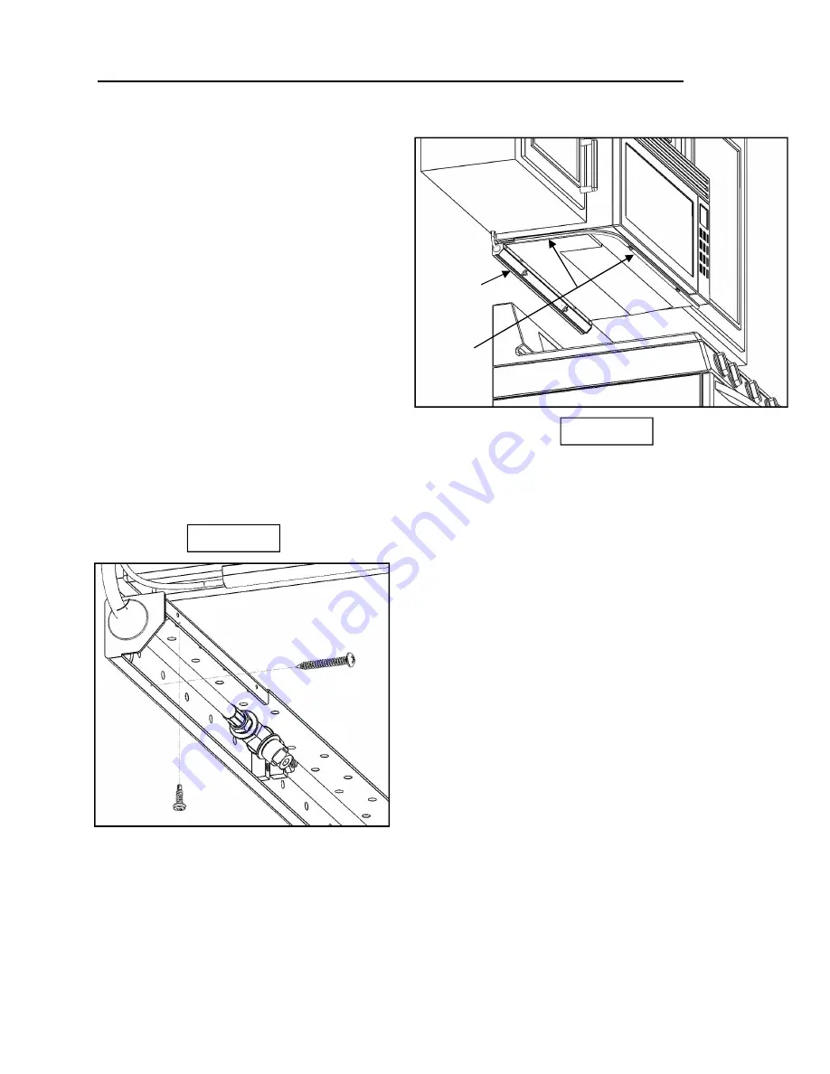
FIGURE 7
FIGURE 8
Distribution
Assembly
Sensor
Assembly
SYSTEM INSTALLATION INSTRUCTIONS (Cont'd)
8. Attach the Sensor Assembly to the bottom of the
Hood/Microwave Hood by placing it near the front
edge and allowing the inline magnets to secure it in
place. It should be installed between 12 and 17
inches away from the rear wall, and as far away
from the wall as the hood will allow within the
specified range (See
Figure 5
). Make sure the
bottom of the hood is cleaned of all grease before
installing the sensor assembly. After installing the
sensor assembly along the front, the remaining
portion of the tube should run along the bottom
side of the hood towards the wall. Next, proceed to
feed the sensor wire through the route you planned
in steps 3-4. (See
Figure 7
)
9. If you are not using the Wireless Tx/Rx, then now is
the best time to run the interconnect cable from the
location of the fuel shut-off up to the cabinet where
the main CPU will be located. You may choose to
run the interconnect cable through a wall mount
conduit or raceway to the bottom of the cabinets
and then follow the same route as the sensor wire,
or you may choose to route it through the wall and
up to the cabinet.
10. The distribution assembly must be centered above
the cooking appliance when it is installed. Firmly
mount the distribution housing in the corner formed
by the back wall and the hood. This is done by
using two self-tapping screws to anchor into the
hood above and two 1-1/4” screws to secure to the
wall behind. Screws in the wall must be located
where they will go into the walls studs or into a wall
anchor. Screws going into the hood must be
located where they will not damage any part of the
hood including wiring, electronic components, etc.
A total of four screws must be installed. After the
housing is mounted, place the Nozzle/Hose
assembly in the housing with the hose on the same
side as your planned route. Slide the 2 clamps onto
the mounting posts in the hosing. Center the
Nozzle assembly and then secure it into place
using the 11/32” Nut Driver to gently tighten the two
clamp nuts onto the stainless steel pipe.
(See
Figure 5, 7, 8 and 9
)
11. Route the stainless steel braided hose through the
route planned in steps 3 and 4. You may need to
place a piece of tape over the end of the quick
coupling to prevent debris from entering the hose
as you pull it through the route. Once the hose is
pulled into the cabinet, route it through the housing
and connect it to the cylinder using the quick
coupling located under the handle.
(See
Figure 6
)
12. Reinstall the main CPU enclosure back onto the Guardian G600-B System Enclosure / Extinguisher Assembly
and tighten the three screws loosened in step 6. Route and connect the sensor wires, solenoid wire and
pressure gauge wire to the main CPU. (See
Figure 2 and 3
) Note: sensor 1 and sensor 2 plugs are
interchangeable and can be plugged into either connector.
13. Attach the green ground wire to an earth ground by using a self-tapping screw and fastening it to a grounded
metal part of the hood. (See
Figure 2
)
Permit Number:
20-04649


