The Roll-Up III
8
Installation
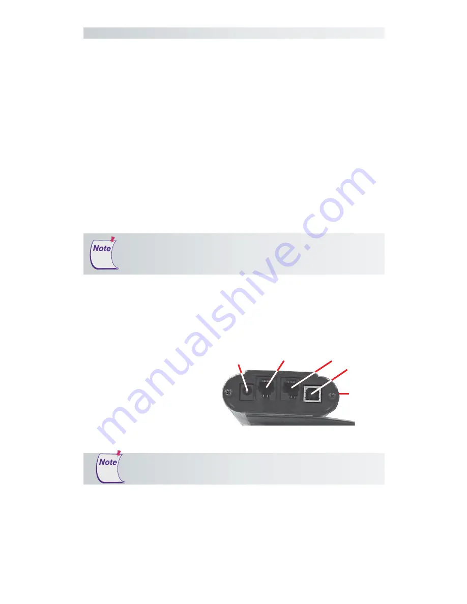
Roll-Up III Connector Panel
Serial
(RS232)
Power
(DC IN)
Transducer
(POINTER)
USB
(USB)
Housing
3
Connect the transducer
– cursor or stylus – to
the appropriate jack on
the digitizer’s Connector
Panel. The connector is
keyed and will fit only
the correct jack. Do not
force it.
Hardware Configuration
When you are using the USB interface, no data output configuration is
required. However, when you choose the optional serial interface, the
Roll-Up III must be configured to send data in a format that is compatible
with the application software. Different applications have different re-
quirements when interacting with a digitizer. The Roll-Up III has been
designed to provide the appropriate serial requirements for a wide variety
of graphic, CAD, and estimating applications using a simple code system.
The SuperSet Menu on the surface of the Roll-Up III is used to enter the
appropriate code for the software you are using. A table in the
Using the
SuperSet Menu
section of this manual lists the SuperSet Codes for a wide
variety of applications.
Determine, if you haven’t already, which communication connection you
will be using—USB or Serial.
1
Select a large, flat, nonmetal surface on which to place the Roll-Up III.
Clear all items from the surface.
2
Remove the Roll-Up III from its cardboard tube container and unroll it
on the selected surface.
Do not attempt to remove the controller from the housing.
Doing so could damage the digitizer and void your warranty.
Conductive materials, inks, or electronic devices on, under, or
near the Roll-Up III can cause improper operation. See the
Troubleshooting
section for more details.


