Geophysical Survey Systems, Inc.
SIR® 20
Manual
MN92-078 Rev F
43
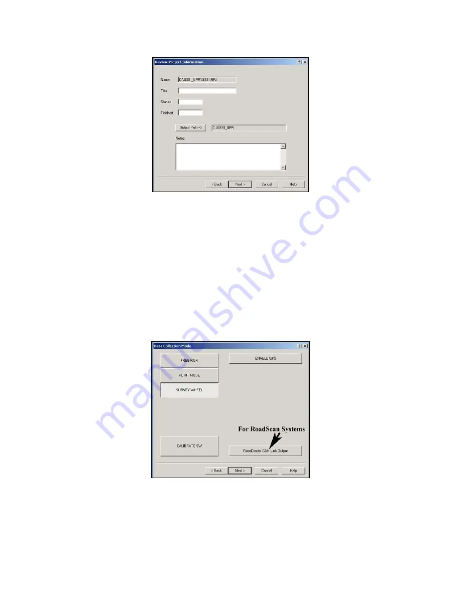
Figure 44: Project Information dialog box.
3
Enter in information to describe your project area. You can give the project a title, a job number, a
start/finish time and add pertinent notes.
•
Note the gray button for Output Path. This is the location where the SIR 20 will store your data
files. This location was set by you in View > Customize.
•
All data input fields on this menu are optional.
4
If you do not wish to add notes, click Next >. A window will open with the heading Data Collection
Mode. The Data Collection Mode window provides you with a choice of the three ways you can
collect 3D radar data.
•
Note the button for Enable GPS. You can collect GPS data along with your grid. See the section
on using a GPS for details on setup.
Figure 45: Data Collection Mode.
•
Click the Survey Wheel button to select the proper data collection mode. You should also see a
button for Calibrate SW. You should always calibrate your survey wheel prior to a survey.
•
Once you have completed survey wheel calibration, click Next > to define grid geometry.
Содержание SIR 20
Страница 1: ......
Страница 4: ......
Страница 6: ......
Страница 12: ...Geophysical Survey Systems Inc SIR 20 Manual MN92 078 Rev F 6 ...
Страница 56: ...Geophysical Survey Systems Inc SIR 20 Manual MN92 078 Rev F 50 ...
Страница 67: ...Geophysical Survey Systems Inc SIR 20 Manual MN92 078 Rev F 61 Figure 65 Migration Comparisons ...
Страница 88: ...Geophysical Survey Systems Inc SIR 20 Manual MN92 078 Rev F 82 ...
Страница 96: ...Geophysical Survey Systems Inc SIR 20 Manual MN92 078 Rev F 90 ...


