Geophysical Survey Systems, Inc.
SIR® 20
Manual
MN92-078 Rev F
4
3
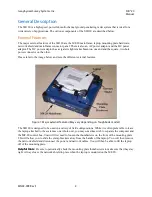
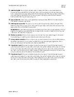
Indicator lights:
The top light will flash amber to indicate that there is good communication
between the laptop and the MF-20. This light will not be lit constantly, but will only flash during
active communication (such as taking data). The bottom light is the MF-20 power light. This will be
lit (green) whenever the MF-20 is on. If you lose power, your laptop will switch to its onboard
battery, but the MF-20 power light will go off.
4
Sync connector:
This is reserved for application requiring multiple SIR 20s to be linked together.
This feature is currently unavailable.
5
SIR 20 power converter:
The power converter is used to keep the laptop battery charged. If the
SIR 20 is plugged into a power source, there will be a green light on the front of the converter. This
light will be lit even if the SIR 20 is turned off.
Helpful Hint:
If your SIR 20 is plugged into a reliable power source but your laptop battery does not
appear to be charging, you should check the two plugs in this converter to make sure there is a good
connection. Also check the 15 amp fuse.
6
Marker connector:
This is a 2-pin connector used to attach a remote marker trigger to the system.
The marker trigger would be used to indicate points of interest in the data.
7
Survey wheel connector:
This is a 4-pin connector used to attach a survey wheel or DMI (distance
measuring instrument). If you are using your SIR 20 for a pavement mapping application, this is
where you will plug in the lead from your wheel-mounted DMI.
8
Transducer 1 port:
This port is hardware channel 1 and accepts a 19 pin GSSI standard control
cable from your antenna. To connect the control cable, line up the 5 indents on the connector with the
5 keys on the male end of the control cable. Then tighten the screw collar on the control cable until
the collar covers the red line on the SIR 20 connector. Only hand-tighten connections. If you are only
using one antenna, connect the antenna to the transducer 1 port.
9
Transducer 2 port:
This port is hardware channel 2 and accepts a 19 pin GSSI standard control
cable from your antenna. To connect the control cable, line up the 5 indents on the connector with the
5 keys on the male end of the control cable. Then tighten the screw collar on the control cable until
the collar covers the red line on the SIR 20 connector. Only hand-tighten connections.
Содержание SIR 20
Страница 1: ......
Страница 4: ......
Страница 6: ......
Страница 12: ...Geophysical Survey Systems Inc SIR 20 Manual MN92 078 Rev F 6 ...
Страница 56: ...Geophysical Survey Systems Inc SIR 20 Manual MN92 078 Rev F 50 ...
Страница 67: ...Geophysical Survey Systems Inc SIR 20 Manual MN92 078 Rev F 61 Figure 65 Migration Comparisons ...
Страница 88: ...Geophysical Survey Systems Inc SIR 20 Manual MN92 078 Rev F 82 ...
Страница 96: ...Geophysical Survey Systems Inc SIR 20 Manual MN92 078 Rev F 90 ...


