3 Set-up and Functional Description
3.1 Block Diagram
1
2
3
18
22
4
5
14
6
7
8
9
10 11 12 13
15
16
17
21
20
19
A
C
Time Base
Shaper
Pulse Generator Processor
RS-232C
Counter
Divider
Pre-Steps
Pre-Steps
Power Supply
Control Logic
Display
Interface
Keyboard
Divider 1:10
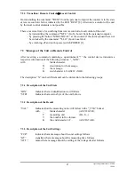
3.2 Description
The unit's internal measuring operation is controlled by a one-chip microprocessor MCS-51
with the help of additional circuits. The processor [18] which gets its time frequency from the
pulse generator [3] can also communicate with superior systems via the serial interface [22].
The time base which is supplied with the standard frequency of 10 MHz [1] provides precise
frequencies for single measuring intervals. The standard frequency is led to a special circuit
via the shaper [2]. This circuit contains an internal predivider of 1:10 [4] and a programmable
dividing decade [5]. Furthermore it provides reference frequencies of 1 MHz and 10 MHz.
The generated measuring intervals are led on the input of the switch- and control logic [14].
The measuring signal passing through channel A is led to a Schmitt-trigger [8] after being set
[6] and boosted [7], and, subsequently, it is converted from ECL to TTL level [9]. This signal
also is led to the input of the switch- and control logic.
The measuring signal passing through channel C is also set and boosted [10, 11], and led to a
fast divider [12] and converted from ECL to TTL. Before passing the switch- and control
logic the high-frequency signal is divided further [13].
The signal gated in [14] is led to a high-speed predivider of 1:10 [15] which is counted by a
decadic counter [16] and shown on an alphanumeric LCD-display [19]. The processor,
thereby, organizes the reading of the keyboard [20], the setting of the control logic, the
resetting of the counting decades and the repetition of the measurement by means of the
interface circuit [17].
7
Operating Instructions UZ 2400
1/2000


