background image


1.3 

 Mains Connection 

 
The design of the unit meets the requirements of safety class I according to EN 61010-1, i. e. 
all metal parts accessible from outside and exposed to contact are connected with the 
protective conducto of the supply network. 
Power is supplied via a mains cable with earthing contact. 
 

1.4  Installing the Power Supply Unit 

 
The unit should not be operated close to equipment that develops heat. 
 

1.5 Switching on 

 
The unit is switched on using the power switch at the front. The power switch separates the 
unit completely from the primary side of the transformer. 
The LED 

ON/OFF

 serves as an operation indicator. 

1.6 EMC 

 
The unit is interference-free according to the EN 50081-1 and EN 50081-2. In order to fulfil 
the limiting values in line with present standards, it is absolutely necessary that only cables 
which are in perfect condition be connected to the unit. The following information applies 
here: 

− 

Metallic or metallized socket cases must be used for interface RS-232C. The socket cases 
and the braided screen of the cables must be connected at the shortest distance possible. 
The signal earth must not be connected to the braided screen. 

− 

After opening and closing the unit ensure that if all the fixing parts and contact springs are 
installed as before that all the screws are fixed and tightly. 


1.7  Inspection and Maintenance 

 
If service is needed, due attention should be paid to the regulations according to VDE 0701. 
The unit should only be repaired by trained personnel. 


4

Operating Instructions UZ 2400 

1/2000 

Содержание UZ 2400

Страница 1: ...2 Specifications 8 4 2 1 Characteristics of Channel A 8 4 2 2 Characteristics of Channel C 9 4 3 Functions 9 4 3 1 Diagnostic Unit Function CHK 9 4 3 2 Frequency Measurement on Channel A FRA 9 4 3 3 Frequency Measurement on Channel C FRC 9 4 3 4 Period Length Measurement on Channel A PER 9 4 3 5 Simple Pulse Counting On Channel A TOT 10 4 4 Time Base 10 4 5 Display 10 4 6 Interface RS 232C 11 5 Co...

Страница 2: ...ion of the Result 17 7 3 3 Description of the Unit Settings 17 7 3 4 Description of the Error 18 7 4 Overview of Commands on Remote Control 18 7 4 1 Group of Common Commands 18 7 4 2 Group of Commands for Reading the Unit Settings 19 7 4 3 Group of Commands for Setting the Unit Functions 19 7 4 4 Group of Commands for Setting the Measurement Parameters 19 7 5 Status Byte 20 7 6 Measuring by Remote...

Страница 3: ...ch should only be done by trained personnel Setting the Operating Voltage 115 V 1 Disconnect the instrument from the mains 2 Remove upper caps and loosen the screws below 3 Identify the mains voltage switch with the following illustration 4 Switch the voltage mains voltage switch slide switch located under the power switch to the indication 115 5 Remove safety cover at the mains plug and replace t...

Страница 4: ...cording to the EN 50081 1 and EN 50081 2 In order to fulfil the limiting values in line with present standards it is absolutely necessary that only cables which are in perfect condition be connected to the unit The following information applies here Metallic or metallized socket cases must be used for interface RS 232C The socket cases and the braided screen of the cables must be connected at the ...

Страница 5: ...tions working incorrectly deviating specifications and so on including unit type and serial number Kindly verify warranty cases by enclosing your supply delivery note Any repairs carried out without reference to a valid warranty will initially be at the owner s expense Should the warranty have expired we will of course be glad to repair the unit as per our General Terms Of Assembly And Service 1 9...

Страница 6: ...0 ms can be measured within the range of and pulses can be counted from 1 to 109 pulses via channel A The trigger level can be set and measuring amplitudes up to 50 V can be attenuated at the ratio of 10 1 on channel A Functions and measuring ranges can be set by means of 4 buttons in the form of a menu and they are clearly depicted on a 16 digit display The unit is supplied with a serial interfac...

Страница 7: ...iding decade 5 Furthermore it provides reference frequencies of 1 MHz and 10 MHz The generated measuring intervals are led on the input of the switch and control logic 14 The measuring signal passing through channel A is led to a Schmitt trigger 8 after being set 6 and boosted 7 and subsequently it is converted from ECL to TTL level 9 This signal also is led to the input of the switch and control ...

Страница 8: ...mm 200 mm Dimensions of packing 310 mm 110 mm 265 mm Weight of universal counter approx 1 8 kg incl packing and accessories approx 2 6 kg 4 2 Specifications 4 2 1 Characteristics of Channel A Frequency range 10 Hz 100 MHz Basic sensitiveness 25 mV sinusoidal signal Vrms Voltage divider 1 1 75 mV on pulses with minimal width of 10 ns Vpp Coupling alternating voltage Input impedance 1 MΩ 20 pF Input...

Страница 9: ...cy Measurement on Channel A FRA Measuring range 10 Hz 100 MHz Measuring times GATE TIME tGate 10 µs 100 µs 1 ms 10 ms 100 ms 1 s 10 s Frequency resolution f 1 tGate max 8 digits Accuracy 1 LSD1 time base error Result display Hz kHz MHz with decimal point 4 3 3 Frequency Measurement on Channel C FRC Measuring range 50 MHz 2 4 GHz Input voltage 25 mV V 2 5 V rms Measuring times GATE TIME tGate 10 µs...

Страница 10: ...ier in noise S V s pulse rate off rise of measured signal portion in the trigger point 4 4 Time Base Start up time 15 min Operational frequency of quartz oscillator 10 MHz Accuracy of frequency setting 5 10 9 Frequency deviations after 24 hours 10 8 Influence of temperature 5 10 9 C 4 5 Display The unit is equipped with a 16 digit alphanumeric LCD matrix display The first three digits indicate the...

Страница 11: ...set with the data transmission rate being optional Data transmission rate 1 200 9 600 Bd Length of data character 8 bit Number of STOP bits 1 Parity none Record without Seperation characters LF AH Reservation of plug connections 1 2 3 4 5 6 7 8 20 1 2 3 4 5 6 7 8 20 FG TXD RXD RTS CTS DSR SG DCD DTR UZ 2400 PC TXD RTS CTS DTR DSR DCD RXD FG SG 11 Operating Instructions UZ 2400 1 2000 ...

Страница 12: ...ollowing functions are selected and displayed FRA frequency measurement channel A FRC frequency measurement channel C PER period length measurement channel A TOT simple pulse counting channel A CHK and so on 5 GATE TIME button The repeated actuating of this button allows the setting of the measuring times 10 µs 100 µs 1 ms 10 ms 100 ms 1 s 10 s and is displayed as follows Gate time 10 µs 100 µs 1 ...

Страница 13: ...if the input voltage divider was set to the ratio 10 1 13 BNC input socket channel C Measuring signals with frequencies of 50 MHz to 2 4 GHz can be led to this input This socket is only for frequency measurements 14 Display MIN The LED indicates an input voltage too low for channel C 15 Display MAX The LED indicates an input voltage too high for channel C Power is supplied by a fused plug for non ...

Страница 14: ...display 9 and on selecting the divider ratio 10 1 the LED 10 1 12 lights up Set the trigger level with the potentiometer 11 so that a stable value is displayed Now set the desired measuring function by means of the button Function 4 see 5 4 No settings have to be made for measurements on channel C 6 2 Frequency Measurement FRA FRC Measuring signals with frequencies between 10 Hz and 100 MHz are le...

Страница 15: ...ll counting decades are reset and the counting process is started The simple pulse counting runs constantly and can only be interrupted by pressing one button 4 5 6 or started again by pressing 7 6 5 Error Messages The measuring decades can be overflown in some cases due to unfavourable selection of the measuring range GATE TIME In this case the faulty result is not displayed but the error message...

Страница 16: ... 5 starts the test The message Test RS 232C ERR documents an interface error On pressing the button MEAS LOCAL the former operation mode is called up 7 2 2 Preparations for the Remote Control Several parameters can be set before switching to remote control The simultaneous pressing of the buttons MEAS LOCAL 7 and FUNCTION 4 causes the assignment of new functions to the buttons FUNCTION GATE TIME a...

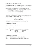
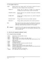
Страница 17: ... the control device transmits a respective information of the following structure _NZK with _ blank character N description for the message Z the message K end character LF ASCII AH The description N can be different and can be divided into the following groups 7 3 1 Description of the Unit State IDN Indicates that an identification word follows STB Indicates that a status byte of the unit follows...

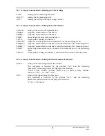
Страница 18: ... until the end character LF are ignored Attention Some PC XT AT 386 computers transmit random signals after being turned on or after hardware resets They might be evaluated as error by the measuring unit 7 4 Overview of Commands on Remote Control 7 4 1 Group of Common Commands IDN identification of unit and software version RST RESET of the unit TRG single measuring cycle according to preceding se...

Страница 19: ... the measuring result FREQC frequency measurement on channel C and transmission of the measuring result PERA period length measurement on channel A and transmission of the measuring result TOTA simple pulse counting on channel A and transmission of the measuring result 7 4 4 Group of Commands for Setting the Measurement Parameters GATE setting of the measuring time on the counter This command is f...

Страница 20: ... within the given time interval error exceeding of command length faultless string command 7 6 Measuring by Remote Control After switching on the counter is in the starting position i e the function CHK the measuring time 100 ms and the divider ratio 1 1 are set The operation is done at the unit The unit is switched to remote control and afterwards is controlled by the respective commands Thereby ...

Страница 21: ...parity 8 data bits 1 stop bit 90 COM 1 ON 100 ON COM 1 GOSUB 510 110 K INKEY 120 IF K CHR 13 THEN GOSUB 210 130 GOTO 100 200 REM data transmission rate 210 INPUT Input message A 220 PRINT 230 PRINT 1 A CHR 10 240 RETURN 500 REM receiving data 510 A INPUT 1 1 520 B B A 530 IF A CHR 10 THEN GOTO 510 540 COLOR 12 550 PRINT received message B 560 COLOR 7 570 B 580 PRINT 590 RETURN 21 Operating Instruc...

Страница 22: ...be done by trained personnel In case of repairs it is vital to ensure that the design characteristics of the unit are not changed thus reducing the safety and that replacement parts match the original ones and are installed properly original state Warning The unit must be separated from all power sources before maintenance work is carried out and before parts or fuses are repaired or replaced 22 O...

Страница 23: ...unit FRA kHz frequency measurement on channel A value unit FRC GHz frequency measurement on channel C value unit PER ms period length measurement on channel A value unit TOT simple pulse counting on channel A value Gate time 100ms adjustment for time of measurement value unit Gate time 1 s Gate time 10 s Gate time 10µs Gate time 100µs Gate time 1ms Gate time 10ms Attenuator 1 1 adjustment for atte...

Страница 24: ...9 2 Declaration of Conformity 24 Operating Instructions UZ 2400 1 2000 ...

Отзывы: