background image

8

Getting started

Locate PC Tool CU 300 in 

Start | Programs | Grundfos PC Tools

 and start it. The 

screen you will see depends on the tool setup chosen the last time the tool was 
started. If you have just installed the tool it has the Standard Tool Setup. This will 
work right away if you are using COM 1 port of your PC and your network connection 
is a direct RS-232 connection (fig. 1, 1a)). In this case a screen image as shown in 
fig. 3 will result (the number of CU 300 icons may differ from your system), and you 
can skip to section The Main window.

General Tool Setup

If your Operation window wrongly shows no CU 300 icons it is likely that the setup of 
your tool does not match your physical connection (e.g. the COM port or network 
connection).

Note:

 In some situations it may take a while (up to 40 seconds) for the tool to estab-

lish communication.
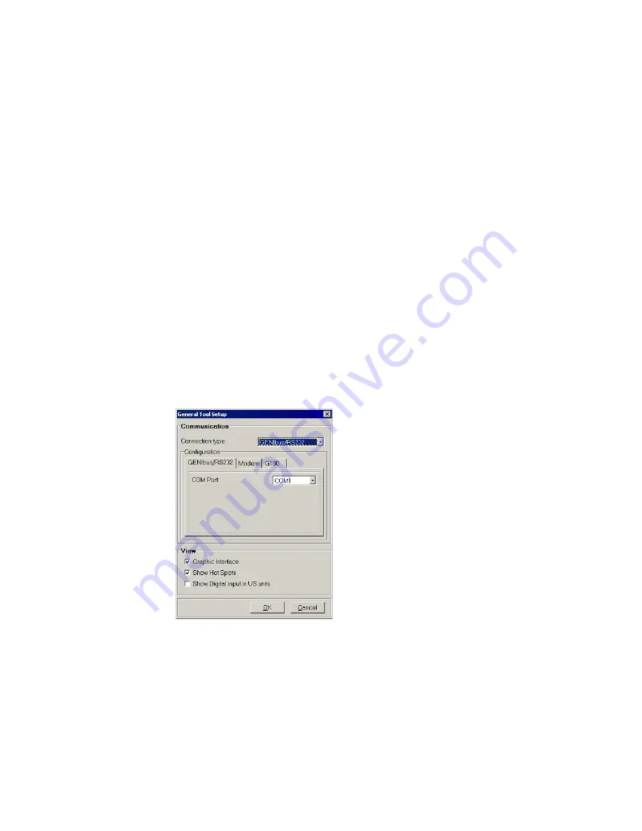
Check the setup by opening the window 

File | General Tool Setup

. Select the cor-

rect connection in the ‘Connection type’ pull-down menu and configure it in the corre-
sponding configuration tab. If you are using modem or G100 with modem, fill in the 
modem initialisation string: ATS0=1.

Digital Input can be shown either in metric units or US units, use the check box 
'Show Digital input in US units' to select the preferred units. The check boxes 'Gra-
phic interface' and 'Show hot spots' can be used to change the appearance of the 
user interface.

Finally click the 

[OK]

 button to save your tool setup to the hard disk. For all connec-

tion types, except those using a modem, communication will now be attempted and 
after a few seconds the icons of the connected units should appear. Consult section 
Fault finding if it does not work. If your network connection is a modem or G100 with 
modem, use 

Dial up

 from the Menu Bar to add phone numbers to the phone book or 

to make a call to the CU 300 site.

Fig. 2 

General Tool Setup window with the standard tool setup

TM01 85

02 27

02

Содержание PC Tool CU 300

Страница 1: ...Installation and operating instructions GRUNDFOS INSTRUCTIONS...

Страница 2: ...2...

Страница 3: ...dows 95 98 NT ME 2000 XP Pentium 100 MHz or higher 16 Mb of RAM memory 9 Mb of hard disk space Monitor resolution 800 x 600 or higher Mouse or other pointing device RS 232 COM port Contents These Inst...

Страница 4: ...300 units or large CU 300 networks Optional connections There are three main options for connection of a PC to a CU 300 1 Using RS 232 for direct connection see fig 1 1a or connection via modem see f...

Страница 5: ...nits Use the CU 300 RS 485 bus ter minals A Y B to connect CU 300 to G100 ac cording to the wiring specification below 1 G100 Radio Modem PLC 1 standard RS 232 cable Twisted pair bus cable with screen...

Страница 6: ...y detects the presence of communication signals on the serial chan nels RS 485 or RS 232 Allow up to 40 s for communication to be established after a power up If communication is switched from one cha...

Страница 7: ...requires the Port 1 DIP switches on the R M P expansion board to be correctly set You need to dismantle the front cover The DIP switch is located at the edge of the circuit board close to the middle S...

Страница 8: ...e setup by opening the window File General Tool Setup Select the cor rect connection in the Connection type pull down menu and configure it in the corre sponding configuration tab If you are using mod...

Страница 9: ...connected units displayed as small icons This is called the Network List The Operation window below shows a situation where the Connection type is GENIbus RS 232 and there are two CU 300 units connect...

Страница 10: ...ion device is modem Note This setup is exclusively visual It does not change anything in the way the tool works the way CU 300 works the way sensors are scaled etc It is therefore possi ble to misfit...

Страница 11: ...sors connected None Modem G100 None Pressure tank Storage tank Water level Top of well pres sure Top of well flow External setpoint None Top of well flow Start stop switch Pipeline flow File Operation...

Страница 12: ...as sensor 1 In the Network List use the mouse to select which CU 300 you communicate with by clicking on its icon Once selected all data you see in the different windows belong to this CU 300 Selecti...

Страница 13: ...osen to be off then a dash is shown in the corresponding sensor window The accuracy of a sensor input is 2 The CU 300 Panel window You open this window by clicking on the upper left corner of the CU 3...

Страница 14: ...will give an explanation to the alarm its possible cause and remedy The Alarm Log cannot be cleared The CU 300 Unit Information window Open this window by selecting Status CU 300 Unit Information or...

Страница 15: ...eous Control mode Open Loop Closed loop Open loop Open loop Setpoint is the pump speed Closed loop CU 300 closed loop control tries to bring the feedback sensor 1 in accordance with the setpoint Butto...

Страница 16: ...stops at low limit Sensor 2 External setpoint Enable Disable Disable Sensor signal used as external analogue setpoint Signal type No sensor 0 20 mA 4 20 mA 0 10 V 2 10 V SPP 1 No sensor Type of electr...

Страница 17: ...e parts are equal to the contents of settings from the Operation window and the three configuration windows Select the parts you would like to program and click Program You can also do the opposite sa...

Страница 18: ...nection on the included CU 300 RS 232 cable is marked black Check for short circuits at the connections Check that the cable is not damaged and that cable con nections if any are sound Check that the...

Страница 19: ...amaged and that cable con nections if any are sound Check that the cable has been made according to the de scription see Wiring specification for the different cable connections page 5 PC Connection C...

Страница 20: ...bus cable must be connected to the right terminals on the CU 300 unit The signal wires to A and B and the screen to Y Check that the connection to A and B are not reversed Check for short circuits at...

Страница 21: ...g the correct COM port in your PC in the window File Tool Setup General Setup the baud rate selected in the window File Tool Setup Gene ral Setup matches the hardware selection on the Radio Modem PLC...

Страница 22: ...he following AT command ATSO 1 Modem connection has been established but the G100 icon turns red and the Status Bar reads Error No communication between PC and G100 This could be due to a bad telephon...

Страница 23: ...Truccazzano Milano Tel 39 02 95838112 95838212 Telefax 39 02 95309290 95838461 Japan GRUNDFOS Pumps K K 1 2 3 Shin Miyakoda Hamamatsu City Shizuoka pref 431 21 Phone 81 53 428 4760 Telefax 81 53 484 1...

Страница 24: ...96 43 28 77 0802 GB Repl V7 15 79 55 0200 Being responsible is our foundation Thinking ahead makes it possible Innovation is the essence...

Отзывы: