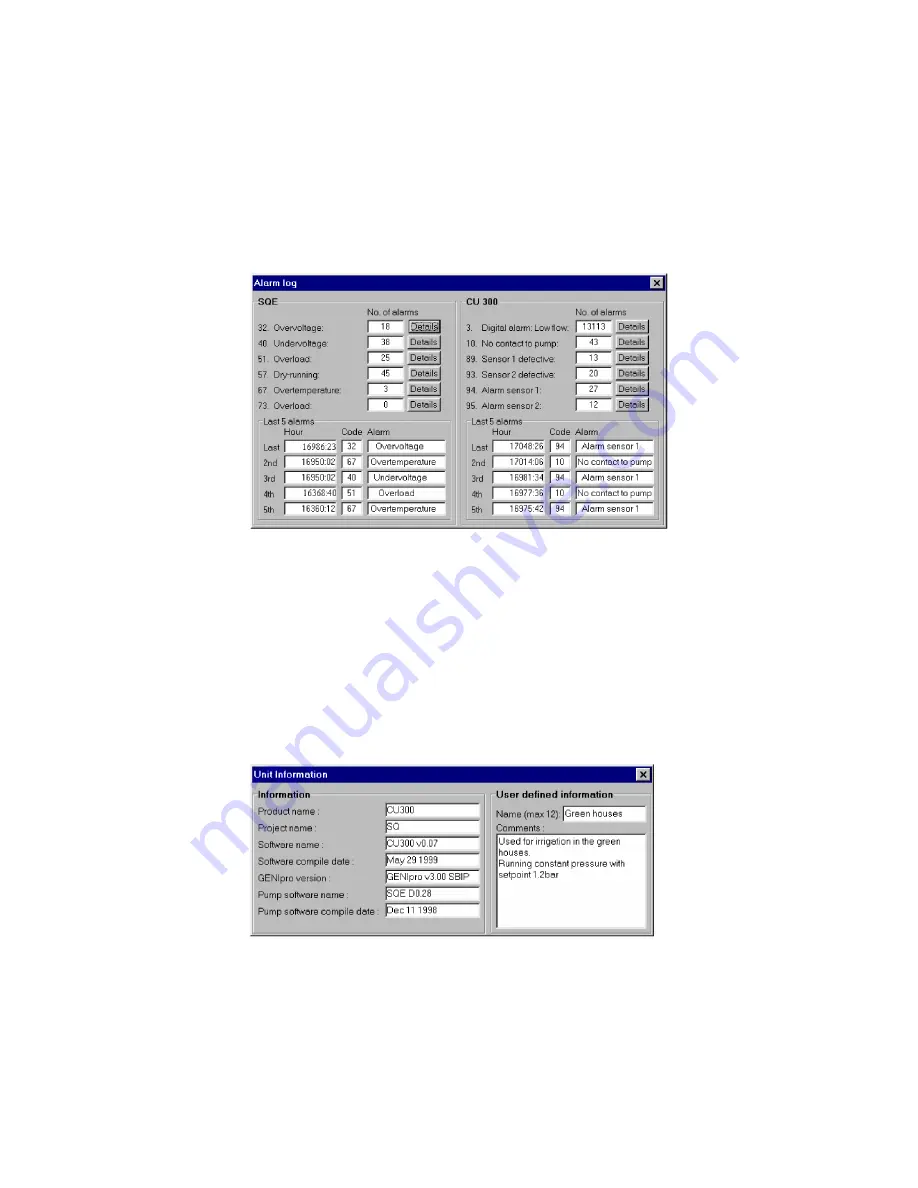
Grundfos PC Tool CU 300 Скачать руководство пользователя страница 14

14

The Alarm Log 
window

You can only open this window by selecting 

Status | Alarm Log

 from the Menu Bar. 

All alarms are divided in two categories, those related to the SQE pump and those 
related to the CU 300 unit. The total number of occurred alarms for the different 
alarm types in each category is recorded.

Below the total alarm number is an alarm log of the 5 last occurred alarms from each 
category shown with a time stamp. When a new alarm different from the latest alarm 
arrives to this alarm log it will push all the previous alarms one position down. Log-
ged alarm No. 5 will be pushed out.

Clicking on the 

[Details]

 button for an alarm will give an explanation to the alarm, its 

possible cause and remedy.

The Alarm Log cannot be cleared.

The CU 300 Unit 
Information window

Open this window by selecting 

Status | CU 300 Unit Information

, or by double click-

ing on the selected CU 300 icon in the Operation window Network List. In the ’Infor-
mation’ field, a series of text strings which are read from the CU 300, and which 
describe the unit, will be displayed. In the ’User defined information’ field, the opera-
tor can name each installation (‘Name’ field) and make a short description of it 
(‘Comments’ field). Both texts will be saved in the PC and tagged to the No. of the 
selected CU 300. 

The text written in the 'Name' field will be added to the icon text in the Operation win-
dow Network List.

TM01 85

07

 0

300

Fig. 7 

The Alarm Log window 

TM01 85

08 03

00

Fig. 8 

The CU 300 Unit Information window 

Содержание PC Tool CU 300

Страница 1: ...Installation and operating instructions GRUNDFOS INSTRUCTIONS...

Страница 2: ...2...

Страница 3: ...dows 95 98 NT ME 2000 XP Pentium 100 MHz or higher 16 Mb of RAM memory 9 Mb of hard disk space Monitor resolution 800 x 600 or higher Mouse or other pointing device RS 232 COM port Contents These Inst...

Страница 4: ...300 units or large CU 300 networks Optional connections There are three main options for connection of a PC to a CU 300 1 Using RS 232 for direct connection see fig 1 1a or connection via modem see f...

Страница 5: ...nits Use the CU 300 RS 485 bus ter minals A Y B to connect CU 300 to G100 ac cording to the wiring specification below 1 G100 Radio Modem PLC 1 standard RS 232 cable Twisted pair bus cable with screen...

Страница 6: ...y detects the presence of communication signals on the serial chan nels RS 485 or RS 232 Allow up to 40 s for communication to be established after a power up If communication is switched from one cha...

Страница 7: ...requires the Port 1 DIP switches on the R M P expansion board to be correctly set You need to dismantle the front cover The DIP switch is located at the edge of the circuit board close to the middle S...

Страница 8: ...e setup by opening the window File General Tool Setup Select the cor rect connection in the Connection type pull down menu and configure it in the corre sponding configuration tab If you are using mod...

Страница 9: ...connected units displayed as small icons This is called the Network List The Operation window below shows a situation where the Connection type is GENIbus RS 232 and there are two CU 300 units connect...

Страница 10: ...ion device is modem Note This setup is exclusively visual It does not change anything in the way the tool works the way CU 300 works the way sensors are scaled etc It is therefore possi ble to misfit...

Страница 11: ...sors connected None Modem G100 None Pressure tank Storage tank Water level Top of well pres sure Top of well flow External setpoint None Top of well flow Start stop switch Pipeline flow File Operation...

Страница 12: ...as sensor 1 In the Network List use the mouse to select which CU 300 you communicate with by clicking on its icon Once selected all data you see in the different windows belong to this CU 300 Selecti...

Страница 13: ...osen to be off then a dash is shown in the corresponding sensor window The accuracy of a sensor input is 2 The CU 300 Panel window You open this window by clicking on the upper left corner of the CU 3...

Страница 14: ...will give an explanation to the alarm its possible cause and remedy The Alarm Log cannot be cleared The CU 300 Unit Information window Open this window by selecting Status CU 300 Unit Information or...

Страница 15: ...eous Control mode Open Loop Closed loop Open loop Open loop Setpoint is the pump speed Closed loop CU 300 closed loop control tries to bring the feedback sensor 1 in accordance with the setpoint Butto...

Страница 16: ...stops at low limit Sensor 2 External setpoint Enable Disable Disable Sensor signal used as external analogue setpoint Signal type No sensor 0 20 mA 4 20 mA 0 10 V 2 10 V SPP 1 No sensor Type of electr...

Страница 17: ...e parts are equal to the contents of settings from the Operation window and the three configuration windows Select the parts you would like to program and click Program You can also do the opposite sa...

Страница 18: ...nection on the included CU 300 RS 232 cable is marked black Check for short circuits at the connections Check that the cable is not damaged and that cable con nections if any are sound Check that the...

Страница 19: ...amaged and that cable con nections if any are sound Check that the cable has been made according to the de scription see Wiring specification for the different cable connections page 5 PC Connection C...

Страница 20: ...bus cable must be connected to the right terminals on the CU 300 unit The signal wires to A and B and the screen to Y Check that the connection to A and B are not reversed Check for short circuits at...

Страница 21: ...g the correct COM port in your PC in the window File Tool Setup General Setup the baud rate selected in the window File Tool Setup Gene ral Setup matches the hardware selection on the Radio Modem PLC...

Страница 22: ...he following AT command ATSO 1 Modem connection has been established but the G100 icon turns red and the Status Bar reads Error No communication between PC and G100 This could be due to a bad telephon...

Страница 23: ...Truccazzano Milano Tel 39 02 95838112 95838212 Telefax 39 02 95309290 95838461 Japan GRUNDFOS Pumps K K 1 2 3 Shin Miyakoda Hamamatsu City Shizuoka pref 431 21 Phone 81 53 428 4760 Telefax 81 53 484 1...

Страница 24: ...96 43 28 77 0802 GB Repl V7 15 79 55 0200 Being responsible is our foundation Thinking ahead makes it possible Innovation is the essence...

Отзывы: