6
2. Product description
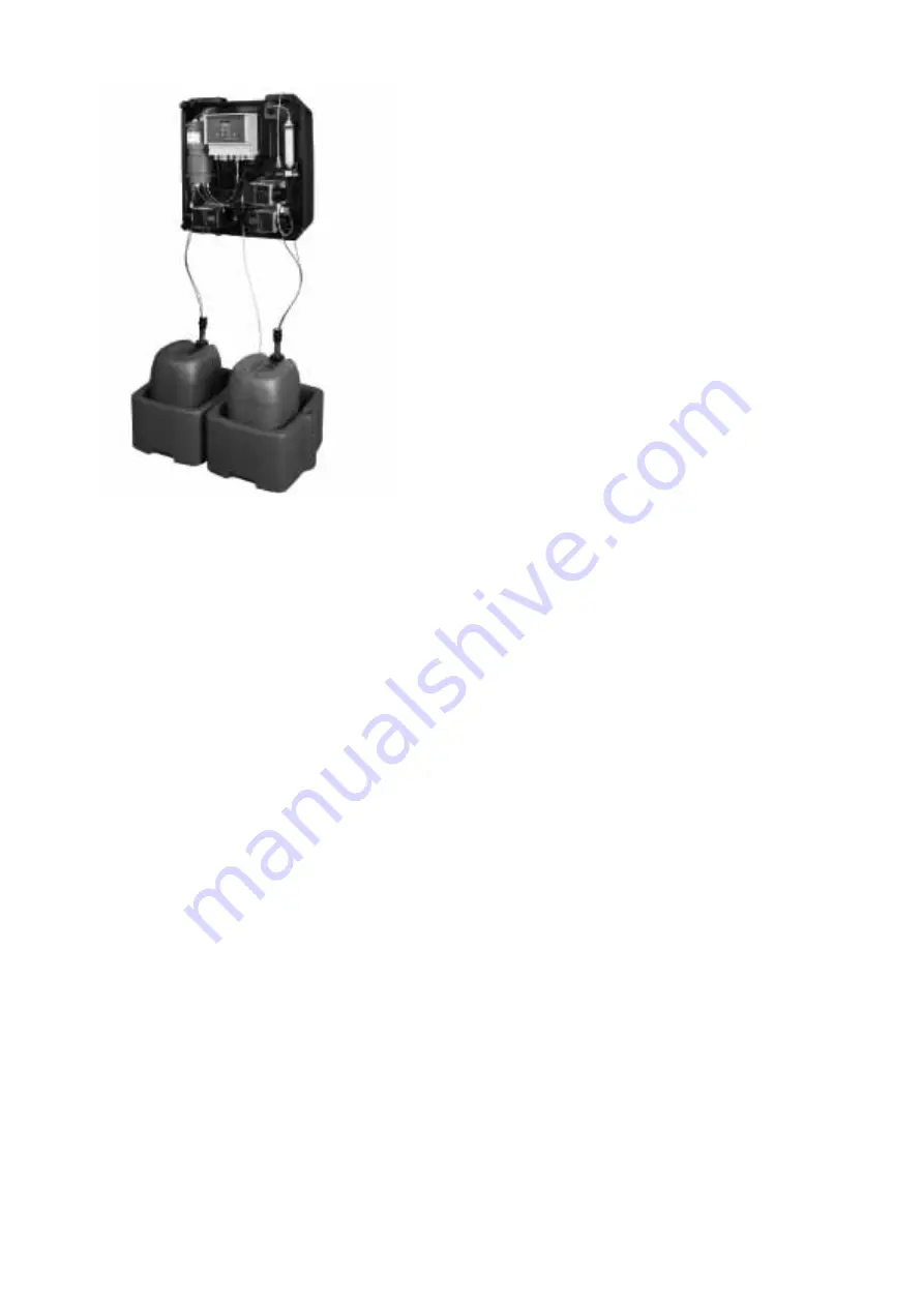
Fig. 1
The Oxiperm Pro – without cover and peripheral
devices
The Grundfos Alldos
Oxiperm Pro
disinfection system is used to
produce and dose chlorine dioxide for the disinfection of drinking
water, process water, cooling water and wastewater.
The device itself consists of a plastic system frame, on which the
internal components are mounted. It is wall-mounted and covered
by a plastic cover.
The chemicals are supplied from two original chemical
containers, which are located in two collecting trays directly under
the system. A suction lance is inserted in each container and is
permanently connected to the corresponding chemical pump in
the device. The suction line cables are used to send "pre-empty"
and "empty" signals to the control system.
The device is connected to two water lines:
•
The drinking water line for supplying dilution water and
flushing water.
•
The main water line to be disinfected, into which the final
ClO
2
solution is dosed.
2.1 Application examples
The
Oxiperm Pro
disinfection system can be used for two
different types of application:
Group 1:
Disinfection of drinking water lines
•
The flow rate of the water in the lines fluctuates greatly
(peak times when water is used for bathing and cooking).
•
The type and level of contamination in the water (disturbance
variables) are not known or are very varied.
•
Examples: Drinking water lines in:
– hotels, multi-storey buildings
– schools, hospitals, nursing homes
– drinks production plants
– small waterworks
– showers in gymnasiums and at swimming pools.
Group 2:
Disinfection of industrial systems
•
The water quantity in these systems is relatively constant.
•
The type and level of contamination in the water (disturbance
variables) are measured and hardly ever change.
•
Examples:
– bottle cleaning plants in breweries
– industrial process water or wastewater systems
– cooling water systems.
2.2 Functional principle
2.2.1 Production of chlorine dioxide
Chlorine dioxide is prepared in the reaction vessel as follows:
Water, hydrochloric acid and then sodium chlorite are added until
a specific level is reached. During the reaction time, a diluted
ClO
2
solution is produced. The reaction vessel is then filled with
water. With a concentration of approximately 2 g of ClO
2
per litre
of water, the final solution flows (as a result of its own hydraulic
effect) through a pipe (overflow) located in the middle of the
reaction vessel into the reservoir tank below.
From the reservoir tank, the dosing pump doses the final ClO
2
solution through to the injection unit, where it is dosed into the
main water line to be disinfected. See section
and
2.2.3 Setpoint-controlled dosing
In "once" operation, the ClO
2
production stops.
In "continuous" operation, the chlorine dioxide production starts
from the beginning in the reactor after a pause.
2.2.2 Flow-rate-proportional dosing
Suitable for group 1 applications – drinking water:
1. The control system is set to proportional controller.
2. A contact water meter or flow meter measures the water
flow
rate in the main water line and continuously sends measured
values to the
Oxiperm Pro
control system.
3. The proportional controller calculates the required ClO
2
dosing volume in proportion to the water flow rate in the main
line.
4. The proportional controller sends the corresponding output
signals to the dosing pump.
5. The dosing pump doses the corresponding quantity of the
ClO
2
solution from the reservoir tank into the main water line.
6. An optional measuring cell monitors the ClO
2
concentration in
the main line.
2.2.3 Setpoint-controlled dosing
Suitable for group 2 applications – industrial water:
1. The control system is set to setpoint controller. A setpoint for
the desired ClO
2
concentration in the main line is specified for
the setpoint controller.
2. A measuring cell monitors the ClO
2
concentration in the main
line.
3. The measuring cell continuously sends actual values for the
ClO
2
concentration to the control system of the disinfection
system.
4. The setpoint controller compares the incoming actual values
with the setpoint and based on the deviation calculates the
quantity of the ClO
2
solution (actuating
variable) that is
required to achieve the desired concentration.
5. The setpoint controller sends output signals to the dosing
pump.
6. The dosing pump doses the corresponding quantity of the
ClO
2
solution from the reservoir tank into the main water line.
A combined controller is also available for applications with
setpoint controller and flow meter (see separate service
instructions).
T
M
03
68
96
45
06


