background image


Deferrisation


GENO-mat FE-Z Deferrisation System 


Order no. 025 153 940-inter   Edited by: nkes-mrie G:\BA-153940-INTER_025_GENO-MAT_FE-Z.DOC 

25 

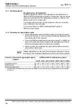
1.3 Reading the 

operating status 

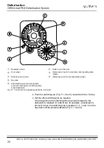
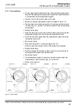
The current operating state may be read from the position of the ref-
erence point (Fig. F-1, Item 8) on the backwash wheel (Fig. F-1, Item 
1). 


The reference point (Fig. F-
1, Item 8) lies opposite 
the reference arrow (Fig. 
F-1, Item 7). 

Operating mode: pure water is available. 

All other settings from the 
reference point (Fig. F-1, 
Item 8). 

Backwash; the backwash wheel (Fig. F-
1, Item 1) turns clockwise; the progress 
of the backwash can be read from the 
position of the reference point (Fig. F-1, 
Item 8). 


The day disk (Fig. F-1, Item 4) turns counter-clockwise once in 12 
days. The red reference arrow (Fig. F-1, Item 3) points to the posi-
tion where a switching pin turned outwards releases a backwash. In 
the operating mode, the distance between the reference arrow (Fig. 
F-1, Item 3) and the following switching pin which is turned outwards 
is an indication for the number of days until the next backwash. 

1.4 How to release a 

manual backwash 

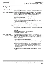
Manual regeneration should be released if 

  the differential pressure of the deferrisation system is more than 

0.3 bar above normal before the timer control releases the back-
wash. 

  the systems are restarted after longer periods of standstill. 

  maintenance or repair work has been carried out.  

Irrespective of the set backwash interval and the time, the backwash 
can be released manually at any time.  
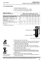
1. Check operating state. 
Only in operating mode: 
2. Turn backwash wheel (Fig. F-1, Item. 1) to the right by one catch 

(pay attention to the snap!). 

The deferrisation system starts the backwash process, the back-
wash wheel (Fig. F-1, Item 1) slowly turns clockwise. After approx. 3 
hours, the backwash is terminated and the white reference point 
(Fig. F-1, Item 8) is located opposite of the black reference arrow for 
the current time again (Fig. F-1, Item 7). 


Содержание GENO-mat FE-Z 20/10

Страница 1: ...Operation Manual GENO mat FE Z Deferrisation system Edition September 2018 Order no 025 153 940 inter...

Страница 2: ...tandards 2 Intended use field of application 3 Function C Product description 12 1 Type plate 2 Technical specifications 3 Intended use 4 Scope of delivery 5 Optional accessories 6 Consumables D Insta...

Страница 3: ...tions into foreign languages electronic storage or copying even in part of this operation manual are only permitted with the explicit written approval of Gr nbeck Wasseraufbereitung GmbH Any type of d...

Страница 4: ...void Manufacturer Gr nbeck Wasseraufbereitung GmbH Josef Gr nbeck Str 1 89420 Hoechstaedt Do Germany Responsible for documentation Markus P pperl Description of the device Deferrisation system Device...

Страница 5: ...systems with the required care This operation manual assists you with important information Therefore please read the complete manual before installing operating or maintaining your system Customer s...

Страница 6: ...adhere to this information will cause serious or life threatening injuries extreme damage to property or inadmissible contamination of the drinking water Warning Failure to adhere to this information...

Страница 7: ...available or b a water stop device see chapter C Accessories must be in stalled 3 5 Indication of specific dangers Danger due to electrical energy Do not touch electrical parts with wet hands Disconne...

Страница 8: ...sposal Comply with the applicable national regulations 5 1 Packaging Dispose of the packaging in an environmentally sound manner 5 2 Product If this symbol crossed out waste bin is on the product Euro...

Страница 9: ...Z deferrisation systems are used for the oxida tion of dissolved iron in the raw water The systems are used for pri vate water supply plants up to maximum values of 3 0 mg l of iron If the systems are...

Страница 10: ...water outlet into the piping system 3 2 Backwashing During the backwash process the filter bed is forcibly flushed from bottom to top and thus loosened up Impurities retained during the filtration pr...

Страница 11: ...ocated on the GENO mat FE Z control valve Que ries and orders will be processed faster if you are able to provide the information listed on your system s type plate Please copy the indi cated informat...

Страница 12: ...g on the iron concentration m h 1 5 2 0 3 0 4 0 5 0 6 0 8 0 Power supply V Hz 230 50 Connected load VA 10 Protection protection class IP 54 Performance data Nominal pressure PN 10 Min max operating pr...

Страница 13: ...special granulate g 105 175 210 350 350 700 1050 Regeneration disinfection interval Regeneration as required disinfection at the latest after 6 months Concentration of preparation 0 35 Total waste wa...

Страница 14: ...is used the GENO oxi plus amount bust be subtracted from the preparation amount Filter layer III Top Filter layer I Bot tom Fig C 2 Filling of filter layers 3 Intended use The system is adjusted to th...

Страница 15: ...egeneration solution Tank has integrated suction device Regeneration device 100 litre FE Z 20 10 FE Z 40 18 153 094 Regeneration device 300 litre FE Z 50 19 FE Z 60 20 153 095 Mounting kit 1 for conve...

Страница 16: ...st glass with 3 chambers and scale Test tablets 0 0 mg l 0 8 mg l 30 tablets Test tablets 0 1 mg l 10 mg l 30 tablets 170 150 6 3 Spare filter filling complete Refer to table C 1 Technical specificati...

Страница 17: ...depending on the iron concentration m h 1 5 2 0 3 0 4 0 5 0 6 0 8 0 Power supply V Hz 230 50 Connected load VA 10 Protection protection class IP 54 Dimensions and weights1 Total height mm 1360 1620 16...

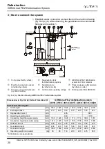
Страница 18: ...company as per 12 2 AVBWasserV German Ordinance on General Conditions for the Supply of Water Observe local and general installation guidelines Provide a drain connection to discharge the backwash wa...

Страница 19: ...board l 5 8 15 18 36 45 88 1 All indications are approximate Filter layer III Top Filter layer I Bottom Fig D 1 Filling of filter layers Centre rising pipe Fill with filter material 1 Fill filter tank...

Страница 20: ...hers on site Control valve operating voltage Drinking water filter BOXER K Fig D 2 a Erection drawing GENO mat FE Z deferrisation system Dimensions in Fig D 2 a Extract from table D 1 GENO mat FE Z de...

Страница 21: ...re is a free outlet min 20mm to the drain Secure the hose with suitable fittings to prevent the hose from moving about regeneration water is pressurised Caution Danger of damage and malfunctions due t...

Страница 22: ...water system immediately prior to commissioning 1 How to start up the system 1 Open the valve at the raw water inlet 2 Open the valve at the pure water outlet 3 Perform a visual check Ensure that no w...

Страница 23: ...e preset time for the backwash 02 00 should be unfavourable for internal reasons set a time which deviates from the current time at the 24 hour disk in order to adjust the starting time for the backwa...

Страница 24: ...e Day disk Steel switching pin in home position moved to centre point in switch position moved outwards Fig F 1 Control unit and operating elements front view 2 Push the switching pin Fig F 1 Item 5 o...

Страница 25: ...ing mode the distance between the reference arrow Fig F 1 Item 3 and the following switching pin which is turned outwards is an indication for the number of days until the next backwash 1 4 How to rel...

Страница 26: ...te must be strictly adhered to DIN EN 806 5 stipulates Inspection every 2 months Maintenance every 6 months Maintenance must be performed by the Gr nbeck s customer service authorised service company...

Страница 27: ...echnician records all maintenance and repair work performed In case of malfunctions this log helps to identify possible sources of error In addition the log documents the proper system maintenance Mak...

Страница 28: ...ti ties refer to Table G 1 We recommend installing a filling tap in the pure water pipe for this purpose Pour the GENO Spezialgranulat special granulate 1 or GENO oxi plus into the tank and mix by mea...

Страница 29: ...ig G 1 picture 1 and the actuator of the control piston has stopped Unplug mains plug Open the ball valve on the back of the control valve and suck the regeneration agent from the connected regenerati...

Страница 30: ...l When starting up the system make sure to record all data on the cover sheet of the operation log and fill in the first column of the check list The customer service technician will fill in a column...

Страница 31: ...GENO MAT_FE Z DOC 31 5 Operation log Customer Name Address GENO mat FE Z deferrisation system Please check appropriate box Serial number Installed by Filter Make Type 20 10 25 13 30 14 40 17 40 18 50...

Страница 32: ...eam and downstream of the system Flow pressure bar upstream and downstream of the system Water meter reading m Iron inlet measured Iron pure water measured Inspections and checks of control unit and c...

Страница 33: ...and downstream of the system Flow pressure bar upstream and downstream of the system Water meter reading m Iron inlet measured Iron pure water measured Inspections and checks of control unit and contr...

Страница 34: ...and downstream of the system Flow pressure bar upstream and downstream of the system Water meter reading m Iron inlet measured Iron pure water measured Inspections and checks of control unit and contr...

Страница 35: ...and downstream of the system Flow pressure bar upstream and downstream of the system Water meter reading m Iron inlet measured Iron pure water measured Inspections and checks of control unit and contr...

Отзывы: