Grizzly G0901 Скачать руководство пользователя страница 6

-4-

Model G0901 (Mfd. Since 09/19)

Controls & 

Components

To reduce your risk of 

serious injury, read this 

entire manual BEFORE 

using machine.

Operator Station & Carriage

Figure 2. Operator controls.

D

E

F

F

G

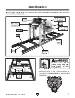
Refer to the following figures and descriptions to 
become familiar with the basic controls and com-
ponents  of  this  machine.  Understanding  these 
items and how they work will help you understand 
the rest of the manual and minimize your risk of 
injury when operating this machine.

Engine

Figure 1. Engine controls.

A

B

C

A.  Engine Speed Lever: Regulates amount of 

air entering engine, controlling engine speed. 
Move  halfway  between  SLOW  (turtle)  and 
FAST  (rabbit)  when  starting  engine.  Adjust 
lever as needed for operation.

B.  Engine Choke Lever: Controls choke valve 

and  air-to-fuel  ratio  in  engine.  Move  lever 
to  OPEN  ( )  position  when  starting  engine 
cold.  Move  lever  to  CLOSED  ( )  position 
after  engine  starts.  Use  CLOSED  ( )  posi-
tion if starting engine warm.

C.  Starter Rope: Pull  several  times  to  start 

engine.  Slowly  retract  starter  once  engine 
starts.

D.  Emergency Stop Button:  Shuts  off  engine 

when  pressed.  Twist  stop  button  to  reset 
before restarting engine. 

E.  Blade Height Handwheel: Raises/lowers 

saw  blade.  One  full  revolution  moves  blade 
approximately 1", with stops at 

1

16

" increments. 

F.  Push Handle: Moves carriage along track.

G.  Throttle Handle: Increases  engine  speed 

when  squeezed.  Fully  engage  throttle  when 
performing cutting operations.

H.  Blade Lubricant Shutoff Valve: Starts/stops 

flow of lubricant onto blade.

I.  Blade Tension Handle: Increases/decreas-

es blade tension (refer to 

Page 23 for more 

information).

H

I

Figure 3. Behind blade cover.

Содержание G0901

Страница 1: ...C WARNING NO PORTION OF THIS MANUAL MAY BE REPRODUCED IN ANY SHAPE OR FORM WITHOUT THE WRITTEN APPROVAL OF GRIZZLY INDUSTRIAL INC AI20609 PRINTED IN TAIWAN V1 12 19 MODEL G0901 28 PORTABLE SAWMILL OWN...

Страница 2: ...g grinding tool integrity and the usage of personal protective equipment The manufacturer will not be held liable for injury or property damage from negligence improper training machine modifications...

Страница 3: ...kpiece Inspection 22 Changing Blade 22 Tensioning Blade 23 Adjusting Guide Rollers 24 Types of Lumber 25 Drying Lumber 26 Cant Sawing 27 Live Sawing 28 Edging 29 Quarter Sawing 30 SECTION 4 ACCESSORIE...

Страница 4: ...de every effort to be exact with the instruc tions specifications drawings and photographs in this manual Sometimes we make mistakes but our policy of continuous improvement also means that sometimes...

Страница 5: ...the controls and features shown below to better understand the instructions in this manual Engine Blade Lubrication Reservoir Blade Cover Blade Tension Handle Throttle Push Handle Blade Height Handwh...

Страница 6: ...B Engine Choke Lever Controls choke valve and air to fuel ratio in engine Move lever to OPEN position when starting engine cold Move lever to CLOSED position after engine starts Use CLOSED posi tion...

Страница 7: ...s from elements and guards operator from entanglement and injury Features a built in limit switch that keeps saw from operating when cover is open M Carriage Brake Secures carriage during service and...

Страница 8: ...g cut or gap in the workpiece after the saw blade passes through during a cutting operation Live Sawing Process of cutting parallel through log or cant from top to bottom Most efficient method of mill...

Страница 9: ...st Ship Upright Yes Engine Main Manufacturer Briggs Stratton Horsepower 13 5 HP Displacement 420 cc Oil Capacity 39 oz Starter Manual Main Specifications Cutting Capacity Max Log Length with included...

Страница 10: ...gal Track Extensions 6 ft Sections Track Leveling 4 Adjustable Feet per Section Other Specifications Country of Origin Taiwan Warranty 1 Year Sound Rating 90 92 dB Approximate Assembly Setup Time 1 Hr...

Страница 11: ...proof DANGEROUS ENVIRONMENTS Do not use machinery in areas that are wet cluttered or have poor lighting Operating machinery in these areas greatly increases the risk of accidents and injury MENTAL AL...

Страница 12: ...moving parts or flying debris Make sure they are properly installed undamaged and working correctly BEFORE operating machine FORCING MACHINERY Do not force machine It will do the job safer and better...

Страница 13: ...nd do not reach over or across sawmill during operation Never support lumber by hand during operation Use non skid safety shoes and hardhat as needed AMPUTATION ENTANGLEMENT Do not oper ate this sawmi...

Страница 14: ...om improperly lifting machine or some of its parts To reduce this risk get help from other people and use a forklift or other lifting equipment rated for weight of this machine The following items are...

Страница 15: ...Rails 2 D Track Section Rear 1 E Track Section Front 1 F Caster Bracket w Brake 1 G Caster Brackets 3 H Track Brackets 2 I Lubricant Reservoir w Hose 1 J Adjustable Feet 8 K Log Supports 2 L Blade 144...

Страница 16: ...14 Model G0901 Mfd Since 09 19 Hardware Recognition Chart USE THIS CHART TO MATCH UP HARDWARE DURING THE INVENTORY AND ASSEMBLY PROCESS 5mm 5mm Flat Head Cap Screw...

Страница 17: ...Extreme conditions for this type of machinery are generally those where the ambient temperature range is outside 41 104 F the relative humidity range is outside 20 95 non condensing or the environment...

Страница 18: ...d 10mm flat washers from carriage then attach lift bar to carriage with removed hardware see Figure 10 The machine must be fully assembled before it can be operated Before beginning the assembly proce...

Страница 19: ...ex bolt between track sections on each side of track with 3 10mm flat washers and 3 M10 1 5 lock nuts as shown in Figure 13 Note Pay attention to the order hardware is added to the hex bolt as it is i...

Страница 20: ...Rail 16 Use forklift or hoist to lift carriage and place it on track Note Carriage must face forward for log sup ports and log clamp to function Log clamp is attached to front rail section 17 Attach c...

Страница 21: ...age use level and adjust front feet so track is level front to back and side to side 23 Repeat Steps 19 22 until track remains level when carriage is moved from one end to the other 24 Tighten M16 2 l...

Страница 22: ...to turn machine OFF 8 WITHOUT resetting Emergency Stop button try to start machine by pulling starter The machine should not start If the machine does not start the safety feature of the Emergency Sto...

Страница 23: ...er guide width 6 Adjust blade height to desired thickness 7 Puts on safety glasses hearing protection and respirator 8 Starts engine 9 Holds down throttle handle and allows blade to reach maximum spee...

Страница 24: ...e any branches that prevent the log from lying evenly against the track and log supports Similarly uneven burls protruding from the log may need to be removed before the log can be sawn Changing Blade...

Страница 25: ...to set tension pro vides a quick and easy method of achieving safe operational blade tension If more precision is required consider using a blade tensioning gauge see Page 32 Figure 25 Blade tension...

Страница 26: ...Figure 26 Guide roller adjustment components Hex Bolt Hex Nut Guide Roller Rod Figure 27 Properly adjusted guide roller 3 Rotate guide roller rod until roller is resting lightly on blade see Figure 2...

Страница 27: ...iful to produce it is the most affordable lumber on the market The majority of construction quality lumber is flatsawn Flatsawn Quartersawn Riftsawn Figure 30 Types of lumber taken from a log To chang...

Страница 28: ...ten used in construction or resawn into smaller pieces of dimensional lumber Figure 31 Example of live sawing a cant into dimensional lumber Drying Lumber Before cutting your first log have a plan for...

Страница 29: ...Note It is essential that the cut face of the cant is secured perpedicular to the track on the first rotation When the first two cuts are perdpendicular the remaining sides will be easy to square to...

Страница 30: ...from log see Figure 35 4 Lower blade the desired thickness of lumber and cut first flitch see Figure 35 Second Cut First Cut Slab Flitch Log Support Log Clamp Figure 35 First cuts to live saw a log 5...

Страница 31: ...are perpendicular to track see Figure 37 Take care that log clamp holds flitches tight against supports 2 Cut to remove bark from the tallest flitches Cut as many flitches as possible without wasting...

Страница 32: ...it Cut a slab about the same size as the first one see Figure 40 To reduce waste make sure the distance between cuts the height of the resulting cant is divisible by the thickness of lumber to be pro...

Страница 33: ...where quartersawn quality wood begins then continue to cut flitches from top to bottom until slab is fully used see Figure 46 Scrap Figure 45 Scrap wood to be cut from slab Quartersawn Lumber Pith Fig...

Страница 34: ...provides you with a direct readout in PSI The Blade Tensioning Gauge is made of light weight cast aluminum for optimum accuracy Bright color coding makes it easy to use and easy to read The Blade Ten...

Страница 35: ...ng moisture content in logs and lumber The XT and Duo Pro also work with brick con crete drywall plaster and carpet so you can find moisture before it becomes a costly problem H4978 Deluxe Earmuffs 27...

Страница 36: ...bearings on this machine except for those with grease fittings are sealed and permanently lubricated Leave these bearings alone until they need to be replaced Do not lubricate them Apply light machin...

Страница 37: ...ge 38 6 Replace blade Page 23 7 Reduce feed rate pressure Finished workpieces have rough surface 1 Excessive feed rate pressure 2 Wrong blade type or TPI for cut type 1 Reduce feed rate pressure 2 Use...

Страница 38: ...23 6 Reduce feed rate pressure Blade does not cut 1 Dull or damaged blade 2 Blade installed backwards 1 Replace blade Page 23 2 Re install blade Page 23 Machine has excessive vibration or noisy opera...

Страница 39: ...re 58 Figure 58 Drive belt tension controls Tension Pulley Belt Tension Bolt Pulley Bracket Hex Nut Belt Tension Hex Nut Figure 57 V belt deflection Bandsaw Wheel Deflection Motor Wheel The G0901 uses...

Страница 40: ...djusting Drive Belt Tension on Page 37 7 Re install blade and close blade cover Replacing V Belts Adjusting Blade Tracking Checking Blade Tracking Tracking refers to how the blade rides on the sawmill...

Страница 41: ...ar and parallel before your saw was shipped so adjusting wheel shaft position should be done as a last resort There are two adjustment bolts with hex nuts that adjust the vertical wheel tilt and a thr...

Страница 42: ...ward turn hex bolt clockwise To tilt outside of wheel backward turn hex bolt counterclockwise 7 Tension blade see Page 23 and inspect blade tracking see Page 38 If tracking is still out of alignment r...

Страница 43: ...t at the time of printing but may not match your machine If you find this to be the case use the wiring diagram inside the motor junction box CAPACITORS INVERTERS Some capacitors and power inverters s...

Страница 44: ...Mfd Since 09 19 READ ELECTRICAL SAFETY ON PAGE 41 Wiring Diagram Wiring Photos 4 3 LIMIT SWITCH AC 15 3A 240V STOP BUTTON ENGINE KEYON KB2 BE101 4 3 2 1 Figure 65 E stop switch box Figure 66 Blade cov...

Страница 45: ...ll parts shown are available for purchase Call 800 523 4777 or visit www grizzly com parts to check for availability 102 101 101 103 104 105 105 106 107 108 130 109 110 110 111 131 112 113 114 115 116...

Страница 46: ...UIDE RAIL FR LH 130 P0901130 GUIDE RAIL RR RH 110 P0901110 GUIDE RAIL CENTER 131 P0901131 GUIDE RAIL RR LH 111 P0901111 GUIDE RAIL FR RH 132 P0901132 TOOL BOX EMPTY 112 P0901112 LOG SUPPORT SHAFT 133...

Страница 47: ...216 218 219 220 221 222 223 224 225 226 227 228 229 230 231 232 232 233 234 234 235 217 236 237 238 239 240 241 242 243 244 244 245 246 246 247 250 248 249 249 246 250 251 253 254 263 259 248 256 256...

Страница 48: ...15 SHOULDER BOLT M16 2 X 65 22 X 10 248 P0901248 LOCK WASHER 6MM 216 P0901216 SPACER 17 6 X 21 4 X 16 249 P0901249 LOCK WASHER 8MM 217 P0901217 HANDLE LOCK PIN 250 P0901250 LOCK WASHER 10MM 218 P09012...

Страница 49: ...301 302 303 304 341 305 306 307 307 308 309 310 311 341 312 314 315 316 317 318 319 320 321 321 336 349 322 323 324 325 326 313 313 327 328 329 330 331 347 341 333 332 334 337 337 335 342 346 335 341...

Страница 50: ...X 12 312 P0901312 TENSIONER WHEEL 339 P0901339 HEX BOLT 7 16 20 X 1 3 8 313 P0901313 SPACER 20 X 52 X 8 340 P0901340 HEX NUT M6 1 314 P0901314 CHAIN TENSION SCREW M10 1 5 X 18 341 P0901341 HEX NUT M8...

Страница 51: ...0 410 REF PART DESCRIPTION REF PART DESCRIPTION 401 P0901401 WHEEL SHAFT 406 P0901406 SAW BLADE 144 X 1 X 035 X 1 3 TPI 402 P0901402 LOCK RING 407 P0901407 NEEDLE BEARING HJ 2028200 IR162020 403 P0901...

Страница 52: ...IDE MOUNT RIGHT 509 P0901509 DRIP TUBE 6 X 8 X 1000MM 502 P0901502 ECCENTRIC ROD M16 2 X 19 122L 510 P0901510 T SLOT BOLT 9 16 M12 1 75 X 44 503 P0901503 ROLLER GUIDE 511 P0901511 LOCK NUT M16 2 504 P...

Страница 53: ...ER 620 P0901620 FLAT WASHER 16MM 606 P0901606 BLADE HEIGHT INDICATOR BRACKET 621 P0901621 HEX BOLT M6 1 X 12 607 P0901607 TORSION SPRING RIGHT 622 P0901622 HEX BOLT M6 1 X 16 608 P0901608 TORSION SPRI...

Страница 54: ...ut warning 6 Keep all combustibles away from engine exhaust port 7 Only remove lumber and scrap from track bed when blade is stopped 8 Never leave engine running while unattended 9 Always stop engine...

Страница 55: ...for incidental contingent special or consequential damages arising from the use of our products The manufacturers reserve the right to change specifications at any time because they constantly strive...

Страница 56: ......

Отзывы: