


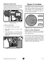

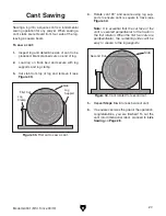


Model G0901 (Mfd. Since 09/19)
-19-
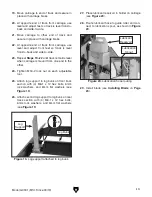
27. Place lubricant reservoir in holder on carriage
(see
Figure 20).
28. Route lubricant hose to guide roller and con-
nect to lubrication spout, as shown in
Figure
20.
19. Move carriage to end of track and secure in
place with carriage brake.
20. At opposite end of track from carriage, use
level and adjust feet so track is level front-to-
back and side-to-side.
21. Move carriage to other end of track and
secure in place with carriage brake.
22. At opposite end of track from carriage, use
level and adjust front feet so track is level
front-to-back and side-to-side.
23. Repeat Steps 19–22 until track remains level
when carriage is moved from one end to the
other.
24. Tighten M16-2 lock nut on each adjustable
foot.
25. Attach log support to log bunk on front track
section with (4) M6-1 x 12 hex bolts, 6mm
lock washers, and 6mm flat washers (see
Figure 19).
26. Attach second log support to log bunk on rear
track section with (4) M6-1 x 12 hex bolts,
6mm lock washers, and 6mm flat washers
(see
Figure 19).
Figure 19. Log support attached to log bunk.
Log
Support
x 8
Log Bunk
Figure 20. Lubrication hose routing.
29. Install blade (see Installing Blade on Page
23).
Lubrication
Spout
Lubricant
Reservoir
Содержание G0901
Страница 56: ......