


-40-
Model G0901 (Mfd. Since 09/19)
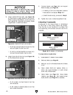
5. Adjust vertical tilt hex bolts (see Figure 62)
so that wheel is perpendicular to the ground.
When making adjustments, loosen one bolt
then tighten the opposite bolt equally. Make
adjustments in small increments.
Small adjustments of tilt bolts make large
changes at edge of wheels. Adjust bolts
incrementally,
1
⁄
4
turn or less at a time.
Figure 62. Vertical tilt hex bolts location.
Bottom Vertical
Tilt Hex Bolt
Top Vertical
Tilt Hex Bolt
— To tilt top of wheel forward, loosen top hex
bolt and tighten bottom hex bolt.
— To tilt top of wheel backward, loosen bot-
tom hex bolt and tighten top hex bolt.
6. Adjust horizontal tilt hex bolt (see Figure 63)
so that blade tracks evenly.
Figure 63. Horizontal tilt hex bolt location.
Horizontal Tilt
Hex Bolt
— To tilt outside of wheel forward, turn hex
bolt clockwise.
— To tilt outside of wheel backward, turn hex
bolt counterclockwise.
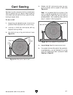
7. Tension blade (see Page 23) and inspect
blade tracking (see
Page 38).
— If tracking is still out of alignment, release
blade tension and repeat
Steps 5–7.
— If blade tracks evenly, proceed to
Step 8.
8. Tighten hex nuts on wheel adjustment hub.
Adjusting Coplanarity
Coplanarity of the blade wheels is determined
by the width of the shims behind the wheels.
Over the life of your machine it is unlikely that
the coplanarity of the wheels will ever need to be
adjusted.
To adjust wheel coplanarity:
1. DISCONNECT SPARK PLUG WIRE!
2. Remove blade (see Page 22).
3. Remove one or both blade wheels from blade
cover.
4. Clean wheel shaft and replace shims so
shims are equal thickness on each wheel
shaft, then install wheels.
Wheels parallel and
coplanar.
Wheels are not
coplanar.
Figure 64. Examples of coplanarity.
5. Install blade (see Page 23), check blade
tracking (see
Page 38), then adjust wheel
shaft position (see
Page 39) as needed.
Содержание G0901
Страница 56: ......