


Model G0901 (Mfd. Since 09/19)
-17-
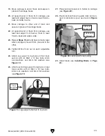
7. Attach (4) adjustable feet to each track sec-
tion. Level track sections by eye and loosely
attach M16-2 lock nut to each foot (see
Figure 12).
Figure 12. Adjustable foot.
Adjustable
Foot
Note:
Tops of adjustable feet must be below the
surface of the track. Feet that rise above track
will interfere with carriage movement.
8. Loosely attach track bracket on each side
of track with (8) M10-1.5 x 25
carriage bolts,
10mm flat washers, and M10-1.5 lock nuts, as
shown in
Figure 13.
9. Insert M10-1.5 x 180 hex bolt between track
sections on each side of track with (3) 10mm
flat washers and (3) M10-1.5 lock nuts, as
shown in
Figure 13.
Note: Pay attention to the order hardware is
added to the hex bolt as it is inserted through
track sections.
Figure 13. Properly assembled track bracket
hardware.
x 8
Track Bracket
Hex Bolt
x 6
Figure 14. Pulling together track sections.
11. Tighten external M10-1.5 lock nut to pull track
sections together (see
Figure 14).
10. Verify top edge of track sections are flush
with each other.
— If track sections are not flush with each
other, level track sections by adjusting
height of adjustable feet.
12. Tighten (2) internal M10-1.5 lock nuts to
secure hex bolt (see
Figure 13).
Figure 15. Securing threaded rod.
x 2
Содержание G0901
Страница 56: ......