


Model G0901 (Mfd. Since 09/19)
-39-
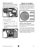
Adjusting Wheel Shaft Position
If blade tracking (see
Page 38) is out of alignment,
the wheel shafts can be adjusted the change the
angle of the wheels. Properly adjusted wheels
should be parallel when the blade is tensioned.
If blade tracking appears to be out of alignment,
we recommend first replacing the blade before
adjusting blade shaft position. A worn belt can
become "bell mouthed" and throw off wheel
coplanarity just enough to cause problems. Guide
rollers out of adjustment can make the blade wob-
ble or wander. Before adjusting wheel shaft posi-
tion, check all of these. The blade wheels were
carefully factory set to be coplanar and parallel
before your saw was shipped so adjusting wheel
shaft position should be done as a last resort.
There are two adjustment bolts with hex nuts that
adjust the vertical wheel tilt and a through bolt
with hex nut that adjusts the horizontal wheel tilt
(see
Figure 60).
Figure 60. Wheel adjustment hub.
Hex
Nuts
Horizontal Tilt
Hex Bolt
Bottom Vertical
Tilt Hex Bolt
Top Vertical
Tilt Hex Bolt
To adjust wheel shaft position:
1. DISCONNECT SPARK PLUG WIRE!
2. Check blade tracking (see Page 38) and
determine which wheel needs to be adjusted,
and in which direction (see
Figure 61).
Wheels parallel and
coplanar.
Wheel is not
vertically aligned.
Wheel is not
laterally aligned.
Figure 61. Examples of wheel alignment.
3. Release blade tension by turning blade ten-
sion handle counterclockwise until handle
slackens.
4. Loosen hex nuts on wheel adjustment hub
(see
Figure 60).
Содержание G0901
Страница 56: ......