


-66-
Model G0887 (Mfd. Since 01/19)
4. Remove both blade guards and blade guard
extension by removing (6) button head cap
screws and flat washers (see
Figure 97).
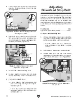
5. On left blade guide, verify back of blade
lightly contacts upper carbide blade guide
(see
Figure 98).
Figure 98. Upper carbide blade guide
adjustment components.
Blade
Cap Screws
Upper
Blade Guide
Figure 97. Location of blade guards and blade
guard extension.
Right Blade
Guard
x 2
Left Blade
Guard
Blade Guard
Extension
x 2
x 2
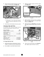
Figure 96. Wheel cover secure screw locations
(2 of 4).
Adjusting Carbide Blade Guides
The carbide blade guides and roller bearings
come adjusted from the factory, but due to blade
changes, shipping, storage, and time they may
need adjustment. Uneven blade wear and crooked
cuts may be the result of improper adjustment.
Tool(s) Needed
Qty
Hex Wrenches 4, 6, 8mm ............................ 1 ea.
Feeler Gauge or Calipers .................................. 1
Adjusting Blade
Guides & Bearings
The blade should be properly tensioned and
tracking correctly before the carbide blade guides
are adjusted (see
Tensioning Blade on
Page 36
and
Adjusting Blade Tracking on Page 68).
To adjust carbide blade guides:
1. Raise headstock high enough to give you
room to work around blade guides.
2. DISCONNECT MACHINE FROM POWER!
3. Open wheel cover by removing (4) button
head cap screws (see
Figure 96).
Содержание G0887
Страница 108: ......