


-44-
Model G0887 (Mfd. Since 01/19)
Adjusting
Support Vise Guide
The support vise guide provides workpiece sup-
port on the outfeed side of the cut, guiding cut-off
pieces down the cutoff chute. The support vise
guide should be adjusted when the cut had been
planned and the workpiece has already been
clamped in the vise. Use the adjustment controls
(see
Figure 52) to support the workpiece close to
where the blade will contact it.
To adjust support vise guide:
1. Loosen position lock handle (see Figure 52).
2. Move vise guide close to planned cut on vise
track (see
Figure 52).
3. Tighten position lock handle to secure posi-
tion.
4. Loosen extension lock handle (see Figure 52).
5. Adjust support vise guide until it contacts
workpiece (see
Figure 52).
6. Tighten extension lock handle.
7. Tighten fine-adjustment handle until plate is
secure against workpiece (see
Figure 52).
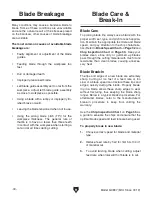
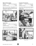
Figure 52. Support vise guide adjustment
controls.
Fine-Adjustment
Handle
Vise
Guide
The Model G0887 is equipped with a work stop
for repetitive cutting operations up to 24" long.
The work stop will need to be adjusted any time it
is removed or repositioned.
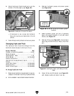
Adjusting Work Stop
To adjust work stop:
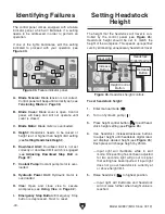
1. Adjust headstock to desired angle.
2. Lower headstock completely.
3. DISCONNECT MACHINE FROM POWER.
4. Screw work stop support rod into hole in
outfeed table with scale facing upward, as
shown in
Figure 53.
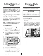
Flat
Edge
Support Rod
Figure 53. Work stop bar installed in table.
Outfeed Table
Hole
Position
Lock Handle
Extension
Lock Handle
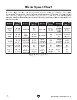
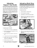
Figure 54. Work stop bracket adjusted to 0
mark.
5. Slide work stop bracket onto support rod,
aligning body with "0" mark on rod scale (see
Figure 54).
0 Mark
Body
Support Rod
Содержание G0887
Страница 108: ......