background image

Model G0678 (Mfd. Since 06/15)

-3-

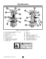
Figure 1. Model G0678 identification.

Identification

A.  Control Panel (refer to Page 17 for details)

B.  Coarse Downfeed Handle

C.  V-Belt Cover

D.  Motor 1 

1

HP, 220V, 3-Phase

E.  Turret

F.  Downfeed Selector

G.  Work Light 110V

H.  Longitudinal (X-Axis) Handwheel

I.  Vertical (Z-Axis) Crank Handle

J.  One-Shot Oiler

K.  Base

L.  Splash Pan

M.  Column

N.  V-Belt Tension Adjustment Bolt

O.  Longitudinal Handwheel

P.  Cross (Y-Axis) Feed Limit Stop Track

Q.  Cross Feed Handwheel

R.  Longitudinal Limit Stop Track

S.  Fine Downfeed Handwheel

Front

Rear

A

B

C

N

O

P

Q

R

S

E

F

G

H

I

J

K

L

M

D

To reduce your risk of 

serious injury, read this 

entire manual BEFORE 

using machine.

Содержание G0678

Страница 1: ...2021 MN WARNING NO PORTION OF THIS MANUAL MAY BE REPRODUCED IN ANY SHAPE OR FORM WITHOUT THE WRITTEN APPROVAL OF GRIZZLY INDUSTRIAL INC TS10934 PRINTED IN TAIWAN V2 01 21 MODEL G0678 VARIABLE SPEED 8 X 30 VERTICAL MILL OWNER S MANUAL For models manufactured since 06 15 ...

Страница 2: ...ng grinding tool integrity and the usage of personal protective equipment The manufacturer will not be held liable for injury or property damage from negligence improper training machine modifications or misuse Some dust created by power sanding sawing grinding drilling and other construction activities contains chemicals known to the State of California to cause cancer birth defects or other repr...

Страница 3: ...eak In 16 SECTION 4 OPERATIONS 17 Operation Overview 17 Basic Controls 17 Table Movement 18 Head Rotation 19 Turret Rotation 20 Setting Spindle Speed 21 Downfeed Controls 22 Loading Unloading Tooling 23 SECTION 5 ACCESSORIES 24 SECTION 6 MAINTENANCE 26 Schedule 26 Cleaning Protecting 26 Lubrication 26 V Belt Tensioning 28 SECTION 7 SERVICE 29 Troubleshooting 29 Adjusting Gibs 31 Adjusting Backlash...

Страница 4: ...ade every effort to be exact with the instruc tions specifications drawings and photographs in this manual Sometimes we make mistakes but our policy of continuous improvement also means that sometimes the machine you receive is slightly different than shown in the manual If you find this to be the case and the difference between the manual and machine leaves you confused or unsure about something ...

Страница 5: ...k Light 110V H Longitudinal X Axis Handwheel I Vertical Z Axis Crank Handle J One Shot Oiler K Base L Splash Pan M Column N V Belt Tension Adjustment Bolt O Longitudinal Handwheel P Cross Y Axis Feed Limit Stop Track Q Cross Feed Handwheel R Longitudinal Limit Stop Track S Fine Downfeed Handwheel Front Rear A B C N O P Q R S E F G H I J K L M D To reduce your risk of serious injury read this entir...

Страница 6: ...gth x Width 19 x 26 in Space Required for Full Range of Movement Width x Depth 68 x 45 in Shipping Dimensions Type Wood Crate Content Machine Weight 966 lbs Length x Width x Height 45 x 45 x 76 in Must Ship Upright Yes Electrical Power Requirement 220V Single Phase 60 Hz Full Load Current Rating 5A Minimum Circuit Size 15A Connection Type Cord Plug Power Cord Included No Recommended Power Cord S T...

Страница 7: ...ble Info Table Length 30 in Table Width 8 in Table Thickness 2 in Number of T Slots 3 T Slot Size 1 2 in T Slots Centers 2 3 16 in Spindle Info Spindle Taper R 8 Number of Vertical Spindle Speeds Variable Range of Vertical Spindle Speeds 200 2250 RPM Drawbar Thread Size 7 16 20 Drawbar Length 12 3 8 in Spindle Bearings Angular Contact Bearings Construction Spindle Housing Quill Chrome Plated Preci...

Страница 8: ...id proof DANGEROUS ENVIRONMENTS Do not use machinery in areas that are wet cluttered or have poor lighting Operating machinery in these areas greatly increases the risk of accidents and injury MENTAL ALERTNESS REQUIRED Full mental alertness is required for safe operation of machin ery Never operate under the influence of drugs or alcohol when tired or when distracted For Your Own Safety Read Instr...

Страница 9: ... moving parts or flying debris Make sure they are properly installed undamaged and working correctly BEFORE operating machine FORCING MACHINERY Do not force machine It will do the job safer and better at the rate for which it was designed NEVER STAND ON MACHINE Serious injury may occur if machine is tipped or if the cutting tool is unintentionally contacted STABLE MACHINE Unexpected movement dur i...

Страница 10: ... or have fingers amputated from contact with rotating cutters You can be blinded or struck by broken cutting tools metal chips workpieces or adjustment tools thrown from the rotating spindle with great force To reduce your risk of serious injury when operating this machine completely heed and understand the following CLEAN MACHINE SAFELY Metal chips or shav ings can be razor sharp DO NOT clear chi...

Страница 11: ...ting or fire may result especially if connected to an undersized circuit To reduce the risk of these hazards avoid over loading the machine during operation and make sure it is connected to a power supply circuit that meets the specified circuit requirements Circuit Requirements for 220V This machine is prewired to operate on a power supply circuit that has a verified ground and meets the followin...

Страница 12: ... these grounding requirements or if you are in doubt about whether the tool is properly grounded If you ever notice that a cord or plug is damaged or worn discon nect it from power and immediately replace it with a new one No adapter should be used with plug If plug does not fit available receptacle or if machine must be reconnected for use on a different type of circuit reconnection must be perfo...

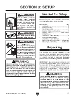
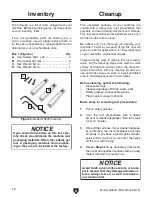
Страница 13: ... a freight claim It is also extremely helpful if you need to return your machine later Unpacking Description Qty Assistants 2 Precision Level 1 Hex Wrench 4mm 1 External Retaining Ring Pliers 1 Safety Glasses 1 Per Person Lifting Straps rated for at least 1500 lbs 2 Power Lifting Equipment rated for at least 1500 lbs 1 Machine Mounting Hardware As Needed Cleaning Solvent Rags As Needed Needed for ...

Страница 14: ...d doing this now will give you a better appreciation for the proper care of your machine s unpainted surfaces There are many ways to remove this rust preven tative but the following steps work well in a wide variety of situations Always follow the manufac turer s instructions with any cleaning product you use and make sure you work in a well ventilated area to minimize exposure to toxic fumes Befo...

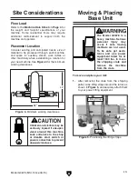
Страница 15: ... seriously injured if unsuper vised around this machine Lock entrances to the shop or disable start switch or power connection to prevent unsupervised use Site Considerations Figure 4 Minimum working clearances 45 68 Moving Placing Base Unit The Model G0678 is a heavy machine Serious personal injury may occur if safe moving methods are not used To be safe get assis tance and use power equipment ra...

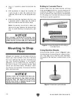
Страница 16: ...he machine to reduce strain on the floor NOTICE We strongly recommend securing your machine to the floor if it is hardwired to the power source Consult with your electrician to ensure compliance with local codes 2 Use a 1 2 wrench to unbolt the mill from the pallet 3 With assistance to steady the machine lift it just enough to clear the pallet and floor obstacles then move it to the prepared loca ...

Страница 17: ...nusual problem during the test run immediately stop the machine disconnect it from power and fix the problem BEFORE operating the machine again The Troubleshooting table in the SERVICE section of this manual can help DO NOT start machine until all preceding setup instructions have been performed Operating an improperly set up machine may result in malfunction or unexpect ed results that can lead t...

Страница 18: ...he spindle direction then turn the mill ON and let it run for another 20 minutes 4 Set the spindle speed at approximately 1800 RPM then repeat Steps 2 3 5 Turn the mill OFF The spindle break in is now complete and the machine is ready for operation 6 Press ON button to turn machine ON Verify motor starts up and runs smoothly without any unusual problems or noises 7 With machine still running use s...

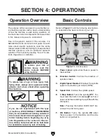
Страница 19: ...erator with a basic understanding of how the machine is used during operation so the machine controls components discussed later in this manual are easier to understand Due to the generic nature of this overview it is not intended to be an instructional guide To learn more about specific operations read this entire manual seek additional training from experienced machine operators and do additiona...

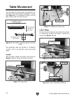
Страница 20: ...The graduated dials are marked in increments of 0 001 with a full revolution moving the table 0 125 Locks Use the table saddle and knee locks shown in Figures 13 14 to secure the table in position Figure 13 Table locks Table Locks Figure 14 Saddle and knee locks Saddle Lock Knee Lock Limit Stops Position the limit stops along the limit stop tracks to confine the distance the table or saddle can tr...

Страница 21: ...otate the head left or right 1 DISCONNECT THE MILL FROM POWER 2 Loosen the four locking hex nuts on either side of the turret see Figure 18 Figure 18 Head rotation locking hex nuts 2 of 4 shown Locking Hex Nuts 2 of 4 Head Rotation Scale 3 Rotate the head to the left or right and use the head rotation scale to determine the angle of rotation 4 Re tighten the four locking hex nuts to secure the hea...

Страница 22: ...rret Rotation Scale 3 Rotate the head and turret around the column to the left or right and use the turret rotation scale to determine the amount of rotation 4 Re tighten the three locking hex nuts to secure the head and turret in place Always lock the turret firmly in place after adjusting the rotation Unexpected move ment of the head during operations could cause the cutter to bind with the work...

Страница 23: ... speed These values are a guideline only Refer to the MACHINERY S HANDBOOK for more detailed information Figure 21 Cutting speed table for HSS cutting tools 2 Measure the diameter of your cutting tool in inches 3 Use the following formula to calculate the required spindle speed RPM for your opera tion Cutting Speed FPM x 12 Recommended Tool Dia in inches x 3 14 Spindle Speed RPM Double if using ca...

Страница 24: ...on E Downfeed Stop Lock Stops downfeed travel when the quill dog reaches this point Set the stop at any position along the downfeed scale then secure it in place by tightening the lock up to it F Graduated Scale Displays quill travel in 0 001 increments when the fine downfeed handwheel is used One full revolution repre sents 0 080 of quill travel G Fine Downfeed Handwheel When this handwheel is en...

Страница 25: ... the top of the spindle Drawbar 4 Push the tool firmly into the spindle taper to seat it then while holding it in place with one hand thread the drawbar into the tool 5 To fully seat the tool into the spindle tighten the drawbar adjustment hex nut down to draw the tool up only until it is snug Note Over tightening the drawbar could make removing the tool difficult Unloading Tooling 1 DISCONNECT TH...

Страница 26: ...rdened vise bed and jaws Sealed bearing system 8200 lbs of clamping pressure Figure 29 T10064 Milling Vise SECTION 5 ACCESSORIES Installing unapproved accessories may cause machine to malfunction resulting in serious personal injury or machine damage To reduce this risk only install accessories recommended for this machine by Grizzly NOTICE Refer to our website or latest catalog for additional rec...

Страница 27: ...Spray Figure 32 Recommended products for protect ing unpainted cast iron steel part on machinery Figure 31 Eye protection assortment H8371 Power Feed for Knee Mills This power feed has all the torque needed for those milling machines with the big tables The infinitely adjustable speed control provides fin ishes not possible with manual control Includes bi directional limit switch with stops mounti...

Страница 28: ...ated and sealed at the factory Simply leave them alone unless they need to be replaced Before adding lubricant clean debris and grime from the devices to avoid contaminating the new lubrication DISCONNECT THE MILL FROM POWER BEFORE PERFORMING LUBRICATION For optimum performance from this machine this maintenance schedule must be strictly followed Ongoing To minimize your risk of injury and maintai...

Страница 29: ...is full then pull the handle see Figure 34 and release it to send the lubricant through the lines Figure 34 One shot oiler Oil Line One Shot Pump Handle Fill Cap Quill Gearing Lubricant Frequency Qty ISO 68 Lubricant or Equivalent Every 8 Hours of Operation 5 Drops Lift the cap of the oil cup shown in Figure 35 to add the lubricant Figure 35 Quill gearing oil cup Quill Gearing Oil Cup Vertical Bev...

Страница 30: ...he motor to the spindle with a V belt With normal use this belt will gradu ally stretch over time When it does perform the following procedures to re tension it Tools Needed Qty Wrench 24mm 1 To tension the V belt 1 DISCONNECT THE MILL FROM POWER 2 Lift the V belt cover then loosen the adjust ment bolt jam nut near the motor see Figure 39 3 Rotate the adjustment bolt until the V belt has approxima...

Страница 31: ...ration 4 Correct motor wiring connections Page 34 5 Test for good contacts correct the wiring 6 Replace loose pulley shaft 7 Test by rotating shaft rotational grinding loose shaft requires bearing replacement 8 Clean off motor let cool and reduce workload 9 Test and repair or replace Machine has vibration or noisy operation 1 Tool holder or cutter is at fault 2 Workpiece alignment is poor 3 Motor ...

Страница 32: ...ing not secure or is damaged 4 Spindle speed feed rate too fast 5 Gibs are too loose 1 Tighten all locks on mill that are not associated with movement for the operation 2 Check that clamping is tight and sufficient for the operation make sure mill vise is tight to table 3 Secure tooling replace if damaged 4 Use correct spindle RPM and feed rate Page 21 5 Adjust gibs properly Page 31 Table hard to ...

Страница 33: ...b that is sandwiched between the stationary and moving surfaces The saddle and knee have a gib on both sides There are two adjustment screws one on each end of each gib that move the tapered gib back and forth increasing or decreasing friction of the slid ing surfaces DISCONNECT THE MILL FROM POWER BEFORE ADJUSTING THE GIBS Loosen one adjustment screw and tighten the other the same amount to move ...

Страница 34: ...The backlash of the longitudinal and cross leadscrew can be adjusted by changing the gap in the leadscrew nuts see Figures 44 45 Use a 5mm hex wrench to tighten or loosen the cap screws on the leadscrew nuts shown in Figures 44 45 then test the amount of backlash by slowly rocking the handwheels back and forth Figure 44 Longitudinal leadscrew nut Longitudinal Leadscrew Nut Gap Gap Cap Screws Cap S...

Страница 35: ...nt at the time of printing but may not match your machine If you find this to be the case use the wiring diagram inside the motor junction box CAPACITORS INVERTERS Some capacitors and power inverters store an electrical charge for up to 10 minutes after being disconnected from the power source To reduce the risk of being shocked wait at least this long before working on capacitors EXPERIENCING DIF...

Страница 36: ... 3 3 0 0 ON Button Stop Button Power Lamp 30V Speed Dial 1 2 3 Digital RPM Readout KP 603A RHYMEBUS Control Panel viewed from behind KP 603A A1 A2 A2 1L1 3L2 5L3 13NO 2T1 4T2 6T3 14NO Contactor NHD C 12D 0 3 0 0 GND Hot Hot Inverter 11 R L1 S L2 U V P PR W L1 L1 L2 L2 1 1 Tb Tc Ta GND V X5 X3 X1 AI X6 X4 X2 V2 V1 V3 13 12 11 GND 1NC 2 4 3NO Direction Switch 6 12 13 6 13 12 220V Motor Wiring Juncti...

Страница 37: ...Model G0678 Mfd Since 06 15 35 READ ELECTRICAL SAFETY ON PAGE 33 Electrical Component Wiring Figure 46 Control panel wiring Figure 47 Motor junction box Figure 48 Inverter contactor and relay wiring ...

Страница 38: ...6 27 28 29 30 31 32 33 34 35 36 37 38 39 40 41 42 43 44 45 46 47 48 49 50 51 52 53 54 55 56 57 58 59 60 61 62 63 64 65 66 10 27 21 22 46 67 Head SECTION 9 PARTS We do our best to stock replacement parts when possible but we cannot guarantee that all parts shown are available for purchase Call 800 523 4777 or visit www grizzly com parts to check for availability ...

Страница 39: ...PRING 48 P0678048 KEY 5 X 5 X 20 15 P0678015 END CAP 49 P0678049 WORM SHAFT 16 P0678016 EXT RETAINING RING 19MM 50 P0678050 WORM 17 P0678017 COARSE DOWNFEED HANDLE 51 P0678051 COMPRESSION SPRING 18 P0678018 KNOB 52 P0678052 KEY 6 X 6 X 15 21 P0678021 CAP SCREW M5 8 X 16 53 P0678053 BUSHING 22 P0678022 SET SCREW M6 1 X 8 54 P0678054 END CAP 23 P0678023 OIL CUP 55 P0678055 PHLP HD SCR M5 8 X 10 24 P...

Страница 40: ...7 3 MOTOR WIRING JUNCTION BOX 138V2 P0678138V2 V BELT B 60 V2 06 15 108 P0678108 HEX BOLT M16 2 X 75 139 P0678139 MOTOR PULLEY 109 P0678109 HEX NUT M16 2 140 P0678140 FLAT WASHER 5MM 110 P0678110 MOTOR BRACKET 141 P0678141 CONTROL BOX 111V2 P0678111V2 SQUARE BOLT M12 1 75 X 40 V2 01 17 142 P0678142 PHLP HD SCR M6 1 X 16 112V2 P0678112V2 LOCK WASHER 12MM V2 01 17 143V2 P0678143V2 SPINDLE SPEED READ...

Страница 41: ...W 207 P0678207 CAP SCREW M6 1 X 25 229 P0678229 TABLE LOCKING SCREW 208 P0678208 COLLAR 230 P0678230 CAP SCREW M6 1 X 16 209 P0678209 EXT RETAINING RING 20MM 231 P0678231 HEX NUT M5 8 210 P0678210 BALL BEARING 6004ZZ 232 P0678232 PHLP HD SCR M5 8 X 10 211 P0678211 CAP SCREW M6 1 X 45 233 P0678233 WAY WIPER 212 P0678212 LEADSCREW BRACKET 234 P0678234 SADDLE GIB 213 P0678213 KEY 5 X 5 X 20 235 P0678...

Страница 42: ...301 339 340 306 307 308 309 310 311 312 313 314 315 316 317 318 319 320 321 322 323 324 325 326 327 328 329 330 331 332 333 334 335 336 337 338 343 344 345 346 347 348 366 307 308 321 318 325 326 316 315 320 318 321 320 321 317 315 316 314 304 303 305 349 350 351 353 354 355 356 357 358 359 360 361 362 363 364 365V2 ...

Страница 43: ...HEX BOLT M6 1 X 30 316 P0678316 SPANNER NUT WASHER 349 P0678349 HEX BOLT 1 2 13 X 2 317 P0678317 BEVEL GEAR 350 P0678350 LOCK WASHER 1 2 318 P0678318 BALL BEARING 6004ZZ 351 P0678351 PIN 10 X 20 319 P0678319 VERTICAL CRANK HOUSING 353 P0678353 PHLP HD SCR 10 24 X 1 2 320 P0678320 CAP SCREW M6 1 X 16 354 P0678354 COLUMN ACCESS PANEL 321 P0678321 KEY 5 X 5 X 20 355 P0678355 PHLP HD SCR M6 1 X 8 322 ...

Страница 44: ...410 P0678410 TOUCH UP PAINT GRIZZLY GREEN 404 P0678404 EYE INJURY HAZARD LABEL 411 P0678411 SHOCK HAZARD LABEL 405 P0678405 DISCONNECT POWER LABEL 220V 412 P0678412 PRE WIRED 220V LABEL 406 P0678406 COVER ENTANGLEMENT LABEL 413 P0678413 ELECTRICITY LABEL 407 P0678407 MACHINE ID LABEL 414 P0678414 CONTROL PANEL LABEL Safety labels help reduce the risk of serious injury caused by machine hazards If ...

Страница 45: ......

Страница 46: ......

Страница 47: ...erty or for incidental contingent special or consequential damages arising from the use of our products The manufacturers reserve the right to change specifications at any time because they constantly strive to achieve better quality equipment We make every effort to ensure that our products meet high quality and durability standards and we hope you never need to use this warranty In the event you...

Страница 48: ......

Отзывы: