Model G0678 (Mfd. Since 06/15)
-19-
Always keep the table locked in place unless
controlled movement is required for your
operation. Unexpected table movement dur-
ing operations could cause the cutter to
bind with the workpiece resulting in damage
to the cutter and workpiece, and possible
personal injury.
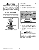
Head Rotation
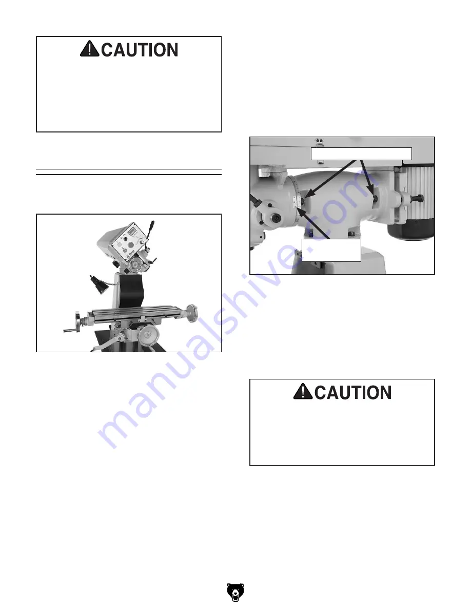
The head rotates 90° from left to right (see
Figure 17).
Figure 17. Head rotated 45° to the left.
Tools Needed
Qty
Wrench 19mm ................................................... 1
To rotate the head left or right:
1. DISCONNECT THE MILL FROM POWER!
2. Loosen the four locking hex nuts on either
side of the turret (see
Figure 18).
Figure 18. Head rotation locking hex nuts (2 of 4
shown).
Locking Hex Nuts (2 of 4)
Head Rotation
Scale
3. Rotate the head to the left or right and use
the head rotation scale to determine the
angle of rotation.
4. Re-tighten the four locking hex nuts to secure
the head.
Always lock the head firmly in place after
adjusting the rotation. Unexpected move-
ment of the head during operations could
cause the cutter to bind with the workpiece
causing damage to the cutter and workpiece,
and possible personal injury.

