Grindex 8120.280 Sandy Inox Скачать руководство пользователя страница 12

3  Product Description

3.1  Products included
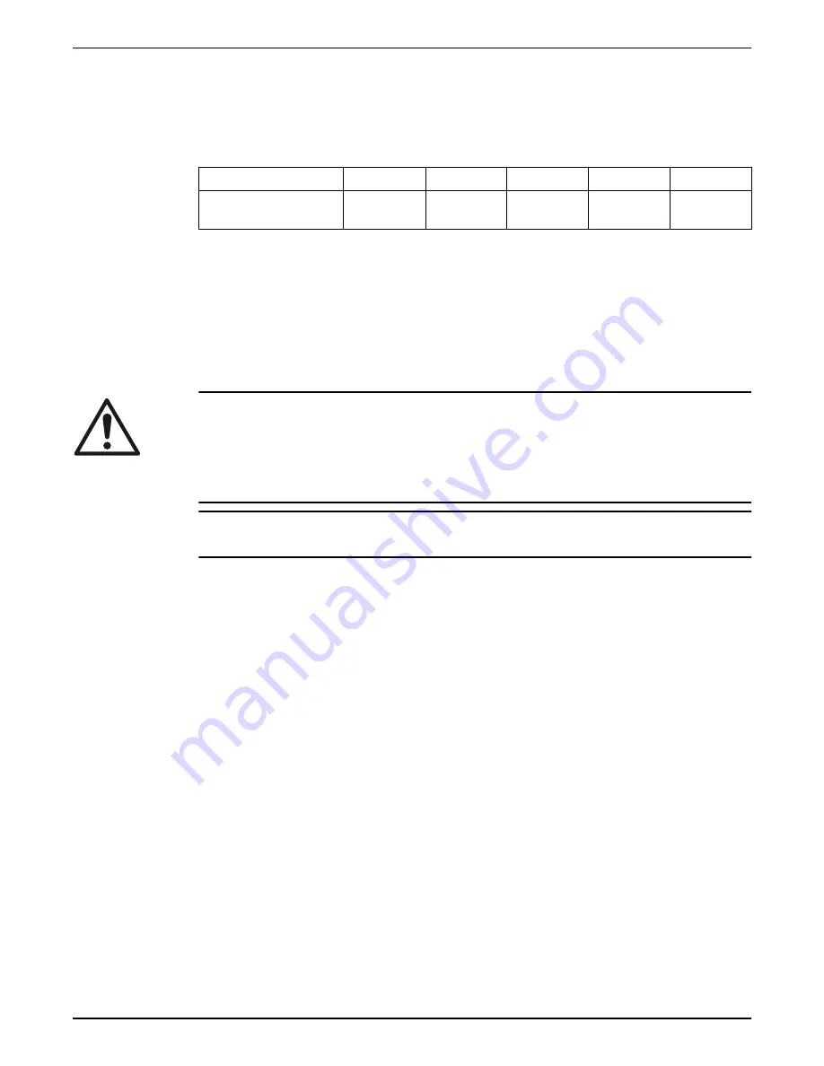
Pump model

Standard Ex-proof MSHA

Drainage Sludge

Sandy INOX

8120.280

X

X

3.2  Pump design

The pump is submersible, and driven by an electric motor.

Intended use

The product is intended for moving waste water, sludge, raw and clean water.

Always follow the limits given in 

Technical Reference

 on page 36. If there is a

question regarding the intended use of the equipment, then contact a sales or

authorized service representative before proceeding.

DANGER: Explosion/Fire Hazard
Special rules apply to installations in explosive or flammable atmospheres. Do

not install the product or any auxiliary equipment in an explosive zone unless it

is rated explosion-proof or intrinsically-safe. If the product is rated explosion-

proof or intrinsically-safe, then see the specific explosion-proof information in

the safety chapter before taking any further actions.

NOTICE:
Do NOT use the unit in highly corrosive liquids.

For information about pH, see 

Technical Reference

 on page 36.

Particle size

The pump can handle liquid containing particles that correspond to the pump

housing inlet.

Pressure class

N

Medium head

Impeller type

Sludge

3.3  Monitoring equipment

The following applies to the monitoring equipment of the pump:

• The stator incorporates thermal contacts connected in series that activate the

alarm at overtemperature.

• The thermal contacts open at 130°C (266°F) and close at 100°C (212°F).

3.4  The data plate

Introduction

The data plate is a metal label located on the main body of the pump. The data

plate lists key product specifications.

3  Product Description

10

8120.280 Sandy Inox Installation, Operation, and Maintenance Manual

Содержание 8120.280 Sandy Inox

Страница 1: ...www grindex com Installation Operation and Maintenance Manual 8120 280 Sandy Inox ...

Страница 2: ......

Страница 3: ...ling and storage 8 2 4 Storage guidelines 8 3 Product Description 10 3 1 Products included 10 3 2 Pump design 10 3 3 Monitoring equipment 10 3 4 The data plate 10 4 Installation 12 4 1 Precautions 12 4 1 1 Hazardous atmospheres 12 4 2 Requirements 12 4 3 Install 13 4 4 Make the electrical connections 14 4 4 1 General precautions 14 4 4 2 Grounding earthing 15 4 4 3 Product specific precautions 16 ...

Страница 4: ...ng 32 7 2 The pump delivers too little or no water 32 7 3 The pump does not start for pumps with SMART 33 7 4 The pump runs but the motor protection trips 34 7 5 The pump stops during operation 34 8 Technical Reference 36 8 1 Application limits 36 8 2 Motor data 36 8 3 Specific motor data 36 8 4 Dimensions and weights 37 8 5 Performance curves 38 Table of Contents 2 8120 280 Sandy Inox Installatio...

Страница 5: ...e proceeding Other manuals See also the safety requirements and information in the original manufacturer s manuals for any other equipment furnished separately for use in this system 1 2 Safety terminology and symbols About safety messages It is extremely important that you read understand and follow the safety messages and regulations carefully before handling the product They are published to he...

Страница 6: ...d to hard hats safety goggles protective gloves and shoes and breathing equipment Make sure that all safety features on the product are functioning and in use at all times when the unit is being operated 1 4 Special hazards 1 4 1 Working in temporary installations Certain industries such as mining or construction have a dynamic nature and require temporary installation of equipment Due to the rugg...

Страница 7: ...minutes 3 Seek medical attention Chemicals or hazardous fluids on skin 1 Remove contaminated clothing 2 Wash the skin with soap and water for at least 1 minute 3 Seek medical attention if necessary 1 5 Protecting the environment Emissions and waste disposal Observe the local regulations and codes regarding Reporting of emissions to the appropriate authorities Sorting recycling and disposal of soli...

Страница 8: ...y to promote the sustainable reuse of material resources Waste from electrical and electronic equipment can be returned to the producer or distributor 1 7 Spare parts CAUTION Only use the manufacturer s original spare parts to replace any worn or faulty components The use of unsuitable spare parts may cause malfunctions damage and injuries as well as void the warranty 1 8 Warranty For information ...

Страница 9: ... around nails and straps 4 If there is any issue then contact a sales representative 2 2 Transportation guidelines 2 2 1 Precautions DANGER Crush Hazard Moving parts can entangle or crush Always disconnect and lock out power before servicing to prevent unexpected startup Failure to do so could result in death or serious injury Position and fastening The unit can be transported and stored either ho...

Страница 10: ...ng while operating or immersed in liquid but the impeller propeller and the shaft seal may freeze if the unit is lifted out of the liquid into a surrounding temperature below freezing Follow these guidelines to avoid freezing damage 1 Empty all pumped liquid if applicable 2 Check all liquids used for lubrication or cooling both oil and water glycol mixtures for the presence of unacceptable amounts...

Страница 11: ...cted with special attention to the seals and the cable entry The impeller propeller must be rotated every other month to prevent the seals from sticking together 2 Transportation and Storage 8120 280 Sandy Inox Installation Operation and Maintenance Manual 9 ...

Страница 12: ...e product is rated explosion proof or intrinsically safe then see the specific explosion proof information in the safety chapter before taking any further actions NOTICE Do NOT use the unit in highly corrosive liquids For information about pH see Technical Reference on page 36 Particle size The pump can handle liquid containing particles that correspond to the pump housing inlet Pressure class N M...

Страница 13: ...y of origin 9 Maximum power consumption 10 Product weight 11 Maximum submersion depth 12 Degree of protection 13 Maximum capacity 14 Rated current 15 Direction of the start reaction 16 Direction of the impeller rotation 17 Maximum head 18 Serial number The first two characters describe the production year 19 Rated voltage 20 Pump model 3 Product Description 8120 280 Sandy Inox Installation Operati...

Страница 14: ... unless it is rated explosion proof or intrinsically safe If the product is rated explosion proof or intrinsically safe then see the specific explosion proof information in the safety chapter before taking any further actions Authority regulation Vent the tank of a sewage station in accordance with local plumbing codes 4 2 Requirements Sedimentation prevention In order to avoid sedimentation when ...

Страница 15: ... in the pumped liquid The pump is equipped with a connection for hose or pipe These requirements and instructions only apply when the installation is made according to the dimensional drawing 1 Run the cable so that it has no sharp bends is not pinched and cannot be sucked into the pump inlet 2 Connect the discharge line The discharge line can be run vertically or horizontally but must be without ...

Страница 16: ...rical shock or burn A certified electrician must supervise all electrical work Comply with all local codes and regulations WARNING Electrical Hazard There is a risk of electrical shock or explosion if the electrical connections are not correctly carried out or if there is fault or damage on the product Visually inspect equipment for damaged cables cracked casings or other signs of damage Make sure...

Страница 17: ...up to six times higher than the rated current Cables These are the requirements to follow when you install cables The cables must be in good condition not have any sharp bends and not be pinched The cables must not be damaged and must not have indentations or be embossed with markings etc at the cable entry The cable entry seal sleeve and washers must conform to the outside diameter of the cable T...

Страница 18: ...owing requirements apply The thermal overload circuit breaker relay must conform to the rated current and motor power input of the actual pump The overload relay should be set as follows Start option Overload relay setting DOL start 1 1 the rated current line current Y D start 0 58 the rated current phase current The pump must be equipped with an external motor starter with a protection system Use...

Страница 19: ...ation sheath or plastic jacket for the control element 5 Power cores 6 Ground earth core with yellow green shrink hose WS004298F Screened SUBCAB 1 5 6 7 8 2 9 3 4 1 T1 T2 and T3 T4 twisted pairs in control element 2 Drain wire in control element tinned copper strands with shrink hose 3 Aluminum and textile layers 4 Insulation sheath or plastic jacket for the control element 5 Power cores 6 Plastic...

Страница 20: ... has sufficient slack The core must stay connected even if the power cores are pulled loose 5 Prepare the power cores a Remove the aluminum foil around each power core b Peel the insulation from each power core 6 Prepare the ends of the ground earth core the power cores and the drain wire Connection type Action Screw Fit cable lugs to the ends Terminal block Fit end sleeves or leave the ends as th...

Страница 21: ...10 5 9 8 6 11 12 17 16 24 22 23 19 20 21 18 25 26 CT 1 Starter equipment and main leads L1 L2 L3 14 Transformer 2 Ground earth 15 Capacitor 3 Functional ground 16 Softstarter 4 Control leads T1 T2 T3 T4 17 Level regulator 5 Phase shifter 18 Contactor start relay or thermal relay 6 Diode 19 Thermal detector in stator 7 Motor cable 20 Thermal detector in main bearing 8 Screen 21 Jumper 9 Pump 22 Ter...

Страница 22: ...1 U1 6 leads Y U1 U5 U2 U6 V1 V5 V2 V6 W1 W5 W2 W6 T1 T2 STATOR LEADS RD GN BN BU YE BK WH YE S T A T O R L E A D S AND T H E R M A L C O N T A C T S 766 71 01 8115 8116 8117 8118 8119 8120 U1 V1 W1 U2 V2 U1 V1 W1 W2 U2 W2 13 14 V2 T1 T2 Terminal plate 6 leads Y D T1 T2 9 leads Y V1 T1 T2 W1 U1 V5 W5 U5 U2 V2 W2 Var 00 01 Var 02 A B C D E U1 V1 W1 U2 V2 W2 13 14 Motor cable and starter unit connec...

Страница 23: ...E GNYE GC L1 BN RD L2 BK BK EXTERNAL STARTER DOL B Terminal plate C A E D Pump EXTERNAL STARTER Y D L1 1BK L3 3BK L2 2BK Motor cable 7 conductors L3 6BK L2 5BK T1 WH L1 4BK T2 WH GNYE V1 Terminal plate U1 W1 V2 13 14 U2 W2 Pump B Terminal plate C A E D Pump Var 00 01 Var 02 A B C D E U1 V1 W1 13 U2 V2 W2 14 INTERNAL STAR DELTA L3 L2 L1 BN RD BK BK GY WH 3 sek SMART F G H A2 16 15 A1 T NC 16 A1 A2 ...

Страница 24: ...tion Action The pump has a CEE plug with internal phase shifter Connect the plug WS006205A The pump has a phase shifter with an on off switch Turn the knob on the phase shifter in either direction WS006207A The pump has neither a CEE plug with internal phase shifter nor a phase shifter with an on off switch 1 Connect the pump to power 2 Switch on the power The pump should start If it does not then...

Страница 25: ...ion from before WS006208A The pump has neither a CEE plug with internal phase shifter nor a phase shifter with an on off switch Transpose two phase leads on the output terminal of the starter NOTICE Do not reverse the phase sequence while the pump is running Temporarily incorrect rotation can occur resulting in damage to motor electronics and rotating parts The pump should start If it does not the...

Страница 26: ...uated this unit for use in swimming pools If used in connection with swimming pools then special safety regulations apply Noise level NOTICE The sound power level of the product is lower than 70 dB A However in some installations the resulting sound pressure level may exceed 70 dB A at certain operating points on the performance curve Make sure that you understand the noise level requirements in t...

Страница 27: ... check that the impeller can rotate freely WARNING Crush Hazard Never put your hand into the pump housing 4 Check that the monitoring equipment if any works 5 Check that the impeller rotation is correct 6 Start the pump 5 3 Clean the pump The pump must be cleaned if it has been running in very dirty water If clay cement or other similar dirt is left in the pump it may clog the impeller and seal pr...

Страница 28: ...heck the explosion risk before you weld or use electrical hand tools Allow all system and pump components to cool before you handle them Make sure that the product and its components have been thoroughly cleaned Before starting work make sure that the work area is well ventilated Do not open any vent or drain valves or remove any plugs while the system is pressurized Make sure that the pump is iso...

Страница 29: ... 20 65 48 127 93 7 220 162 434 320 70 80 2 7 2 5 4 4 9 0 6 6 22 16 44 32 76 56 187 138 364 268 629 464 1240 915 100 4 1 3 8 1 6 14 10 34 25 66 49 115 84 8 248 183 481 355 Table 4 Steel torque Nm ft lbs Propert y class M4 M5 M6 M8 M10 M12 M16 M20 M24 M30 8 8 2 9 2 1 5 7 4 2 9 8 7 2 24 18 47 35 81 60 194 143 385 285 665 490 1310 966 2 10 9 4 0 2 9 8 1 6 14 10 33 24 65 48 114 84 277 204 541 399 935 6...

Страница 30: ...ed 40 C 104 F 6 3 1 Inspection Regular inspection and service of the pump ensures more reliable operation Service item Action Visible parts on the pump and installation 1 Check that all screws bolts and nuts are properly tightened 2 Check the condition of the pump casing strainer cover lifting handles eye bolts ropes chains and wires 3 Check for worn or damaged parts 4 Adjust and or replace if nec...

Страница 31: ...y sharp bends and are not pinched Cooling system If the flow through the system has been partly restricted then rinse and clean Level sensors or other sensor equipment 1 Check the functionality 2 Repair or replace any damaged equipment 3 Clean and adjust the equipment Starter equipment 1 Check the condition and functionality 2 Contact an electrician if necessary Insulation resistance in the stator...

Страница 32: ...inside the chamber may cause parts or liquid to be propelled with force Be careful when opening Allow the chamber to de pressurize before removal of the plug 3 Turn the pump so that the oil hole faces downwards and let the oil run out into a container Fill with oil 1 Replace the oil screw O ring 2 Put one of the oil screws back and tighten it 3 Turn the pump so that the oil hole faces upwards and ...

Страница 33: ...e and must therefore not be reused A WS001835A 6 5 2 Install the impeller 1 Fit the guide plate 2 Slide the impeller carefully onto the shaft so that the key fits into the keyway in the impeller 3 Place the washer on the impeller screw 4 Fit the impeller onto the shaft 5 Tighten the impeller screw 6 Maintenance 8120 280 Sandy Inox Installation Operation and Maintenance Manual 31 ...

Страница 34: ... The discharge hose is pinched or kinked Make sure the hose is as straight as possible The hose is too long or the hose is undersized Try the following 1 Make sure the right hose size is used Shorten the hose if possible 2 Change to a larger pump 3 Check that the lifting head of the pump corresponds to the given data The easiest way to do this is to use a pressure gauge The pump has insufficient c...

Страница 35: ... while the motor is running Doing so may cause incorrect rotation resulting in damages to the motor electronics and the rotating parts Respect the 8 seconds delay WS002616A WS002615A Figure 5 Phase shifter On Off switch If no glove or phase shifter is used then shift two phase conductors in the cabinet If the problem persists then contact a sales or authorized service representative Always state t...

Страница 36: ...t a sales or authorized service representative Always state the product number and the serial number of the pump see Product Description on page 10 7 5 The pump stops during operation Cause Remedy The cable is broken Replace the cable The pump is equipped with a special cable that must be replaced with a cable of the same type It can be obtained directly from Grindex or from a representative NOTIC...

Страница 37: ...ct a sales or authorized service representative Always state the product number and the serial number of the pump see Product Description on page 10 7 Troubleshooting 8120 280 Sandy Inox Installation Operation and Maintenance Manual 35 ...

Страница 38: ...tion 8 2 Motor data Feature Description Motor type Squirrel cage induction motor Frequency 50 Hz or 60 Hz Supply 3 phase Starting method Direct on line Star delta Maximum starts per hour 30 evenly spaced starts per hour Code compliance IEC 60034 1 Voltage variation without overheating 10 if it does not run continuously at full load Voltage imbalance tolerance 2 Maximum frequency variation for pump...

Страница 39: ... rpm Rated output 6 7 kW 9 0 hp Voltage V Rated current A Starting current A 220 Y parallel 22 153 230 Y parallel 21 161 440 Y serial 11 77 460 Y serial 11 81 575 D 8 6 67 600 D 8 5 70 8 4 Dimensions and weights Sandy INOX 1 480 mm 18 9 in 755 mm 29 7 in 1 Throughlet diameter 46 mm 1 8 in Weight 86 kg 190 lbs 8 Technical Reference 8120 280 Sandy Inox Installation Operation and Maintenance Manual 3...

Страница 40: ...0 24 4 2 6 8 10 12 14 16 Q l s 7 P1 kW H m 4 5 3 6 1 2 WS006404A Figure 6 50 Hz 0 2 4 6 8 10 12 14 16 0 50 100 150 200 250 Q l s usgpm 0 5 10 15 20 0 20 40 60 80 25 H ft m 8 P1 hp kW 0 1 2 3 4 5 6 7 0 2 4 6 8 10 WS006405A Figure 7 60 Hz 8 Technical Reference 38 8120 280 Sandy Inox Installation Operation and Maintenance Manual ...

Страница 41: ......

Страница 42: ......

Страница 43: ......

Страница 44: ...00 Fax 46 471 24 74 01 http tpi xyleminc com Visit our Web site for the latest version of this document and more information The original instruction is in English All non English instructions are translations of the original instruction 2011 Grindex 898436_6 0_en US_2019 12_IOM_8120 280 Sandy Inox ...

Отзывы: