


D 4. Remove the breakaway plates and re-drill the
holes in the breakaway plates only to 1/8".
D 5, Fasten the breakaway plates to the beams
using six #4 x 5/8" screws.
#4x5/8" SCREW
INSTALL THE LANDING GEAR
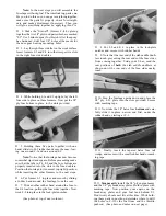
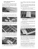
D 1. Turn the fuselage upside down and position
the 5/32" wire main L.G. (landing gear) on the ply
L.G. plate. Set the four nylon L.G. straps in place
and mark the location for the eight screw holes. Drill
3/32" (or slightly smaller) holes at the marks.____
D 2. Temporarily mount the main LG using the
nylon straps and the #4 x 1/2" screws.
4 - 4 0 x 1 " BOLT
#4x1/2" S C R E W
D 3. Temporarily mount the nylon nose gear bearing
using four 4-40 x 1" bolts screwed into the 4-40 blind
nuts previously installed.
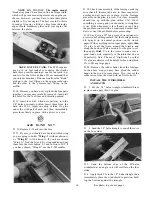
PREPARE THE NOSE GEAR
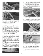
D 1. Referring to the steering arm drawing here,
cut off about 3/16" of the steering arm so it will clear
the fuse triplers. Drill out the end hole to 5/64"diame-
ter for pushrod wire clearance.
TRIM 3/16" HERE
D 2.Assemble the nose gear steering arm which
consists of a nylon arm, a 5/32" wheel collar and a
6-32 x 3/16" screw.
D 3. Place the steering arm assembly into the nose
gear bracket making sure that the wheel collar open-
ing on the steering arm is down and the screw is
facing out.
11
D 4. Referring to the nose gear diagram on the plans,
slide the nose gear wire through the holes in the
nose gear bearing and wheel collar/steering arm.
Tighten the screw, making sure the steering arm is
at the angle shown on the top view of the fuselage.
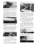
D 4. If you are a young person, you should ask
an adult to help you with the following step:
Using a side cutter, cut off the excess bolt length
sticking out behind F-l. You must wear eye protec-
tion when doing this! Note: An alternate method
is to mark the bolts with an indelible marker, remove
them from F-l, and cut them off at the marks with
a side cutter, hacksaw or a Dremel cut-off wheel.
(See photo, top of next column.)
CUT THE NOSEGEAR PUSHROD
OPENING
D 1. Mark and drill a 1/8" hole through Former F-l
in the position shown on the F-l drawing on the plan.
This hole is for pushrod clearance.
See photo, top of next page
12


