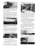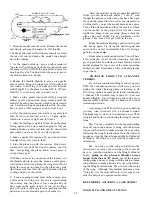
D 17. Screw the nylon clevises back on the rear ends
of the pushrods. Pry the clevises open with a screw-
driver and hook them up to the outer holes in the
nylon elevator and rudder horns. Twist the pushrods
slightly, so the rods come out of the fuse side slots
without binding.
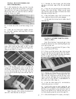
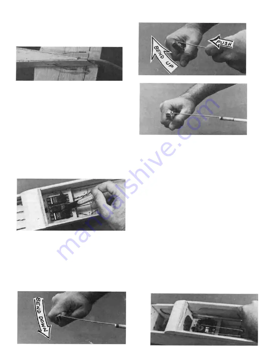
B-Bend up with pliers.
C-Finish Z-bend.
D 18. Temporarily hook up the receiver, battery
pack, switch and servos. Read the instruction man-
ual for your radio to learn how to do this.
D 19. Center the "trim tabs" on your radio transmit-
ter for the elevator, aileron and rudder controls. The
trim tab for the throttle should be pushed all the
way forward.
D 20. Turn on the transmitter and receiver so the
servos rotate to their normal "centered" positions.
Now turn off the receiver and transmitter (in that
order).
D 21. With the rudder centered (straight with the
fin) lay the front part of the rudder pushrod across
the hole in the servo wheel where it will attach. Using
an indelible marker, make a small mark on the push-
rod at the hole location.
D 22. Center the elevator and mark the pushrod
where it goes across the hole in the elevator servo
wheel.
L_] 23. Remove the elevator and rudder pushrods from
the fuselage and make "Z"-bends in the pushrods at
the marks you just made. Here's how...
A-Bend down with pliers.
D 24. Now you may re-install the pushrods and in-
sert the Z-bends into the servo wheels. Note: To do
this you must remove the servo wheel from the servo,
drill out the hole in the servo wheel to 5/64" diameter,
work the Z- bend into the hole, and replace the servo
wheel on the servo.
D 25. Turn the radio on, and check the movement
of the elevator and rudder. To re-center the elevator
and rudder, turn the clevis on the rear end of the
pushrod.
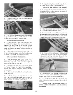
D 26. From die-cutting scrap, cut two pieces of 1/8"
plywood 1/4" wide and 2-3/4" long. Glue these "push-
rod braces" to the front of F-4, above and below the
pushrod dowels, as shown in the drawing of F-4 on
the bottom of the fuse plan.
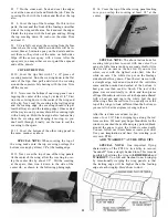
D 27. To provide adequate movement to move the
throttle from full power to idle, you will probably
have to use a longer servo arm than the small wheel
which is standard on the servo. Take one of the 4-arm
servo arms and cut off three of the arms.
D 28. With the long arm attached to the throttle
servo, as shown on the fuse plan top view, lay a pencil
across the top of the arm and make a mark on the
back of F-2. Also make a mark for the nose gear
pushrod hole. Note: Also see the drawing of F-2 near
the bottom of the plan.
27


