


Note: In the next steps you will assemble the
fuselage without glue! The interlocking parts ena-
ble you to do this so you can get everything together,
make sure the parts fit properly, check for straight-
ness and make adjustments if necessary. Then you
will glue everything together by applying thin CA.
D 2. Make the "firewall" (Former F-l) by gluing
together the two 1/8" plywood parts which are marked
"F-l". Use 5 minute epoxy for this job. After the epoxy
has hardened, drill four 1/8" holes at the marks for
the nose gear bearing mounting holes.
D 3. Lay the right fuse side flat on the work surface.
Insert formers F-l and F-2 into their respective slots
in the right fuse side doubler.
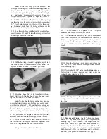
D 8. Put F-5 and F- 6 in place in the lock-plate
notches and secure with rubber bands.
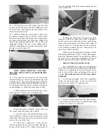
D 9. Note that the rear end of the stab saddle doub-
lers touch, preventing the rear ends of the fuse sides
from coming together. Using your T-bar, sand the
rear portions of both the stab saddle doublers as
shown until the rear ends of the fuse sides nearly
touch.
D 4. While holding F-l and F-2 upright, lay the left
fuse side in place on these formers. Now put the 1/8"
ply fuse bottom in place in the slots provided.
D 5. Holding these five parts together with one
hand, slide two #62 rubber bands over the nose, leav-
ing one around F-l and one around F-2.
Note: Notice that the fuselage has now become
somewhat rigid and square. Before proceeding make
sure that the tabs in F-l, F-2 and the fuse bottom are
properly inserted into the slots in the fuse doublers.
Position the fuselage in its normal (upright) position
while inserting the other formers in the next steps.
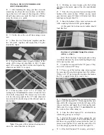
D 6. Put former F- 3 in place and secure by sliding
a rubber band around the fuselage from the rear.
D 7. Slide another rubber band around the fuse to
the F-4 location, pulling the fuse sides together. Now
work F-4 into place in the lock-plate notches.
(See photo at top of next column.)
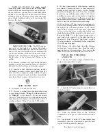
D 10. Turn the fuselage upside down and place the
3/8" ply L.G. plate into the slots provided. Secure
with masking tape.
D 11. Now take the 1/8" balsa fuse bottom and care-
fully slide it in place, narrow end first, under the
rubber bands, starting at F-3.
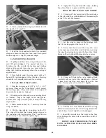
D 12. Finally, insert the tapered balsa fuse tail
wedge, and secure with a small rubber band or mask-
ing tape.
D 13. Temporarily install the 3/8" ply engine beams
and the 1/4" ply breakaway plates. Hold in place with
masking tape. Now position your engine on the
breakaway plates and your fuel tank behind F-l.
Don't worry about exact fits at this time. While hold-
ing these parts in position, determine where to drill
the holes in F-l for the fuel lines and the throttle
pushrod. (See photo and notes on next page.)


