8
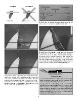
Hinge Line
Hinge Line
CORRECT
INCORRECT
Hi
❏ ❏ ❏ ❏
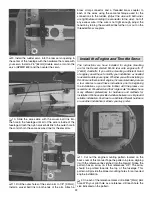
7. Place a nylon control horn in line with the outer
hole in the servo arm. When positioned properly the control
horn will rest on a hardwood plate in the aileron. Mark the
location of the mounting holes onto the aileron. Drill a 3/32"
[2.4mm] hole on the marks, drilling through the plywood plate
but not
through the top of the aileron. Attach the horn to the
aileron with four #4 x 1/2" [12.7mm] screws.
❏ ❏ ❏ ❏
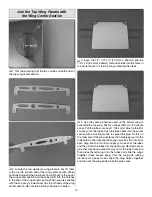
8. The parts shown are required for making the
servo pushrod. Locate all the needed components.
❏ ❏ ❏ ❏
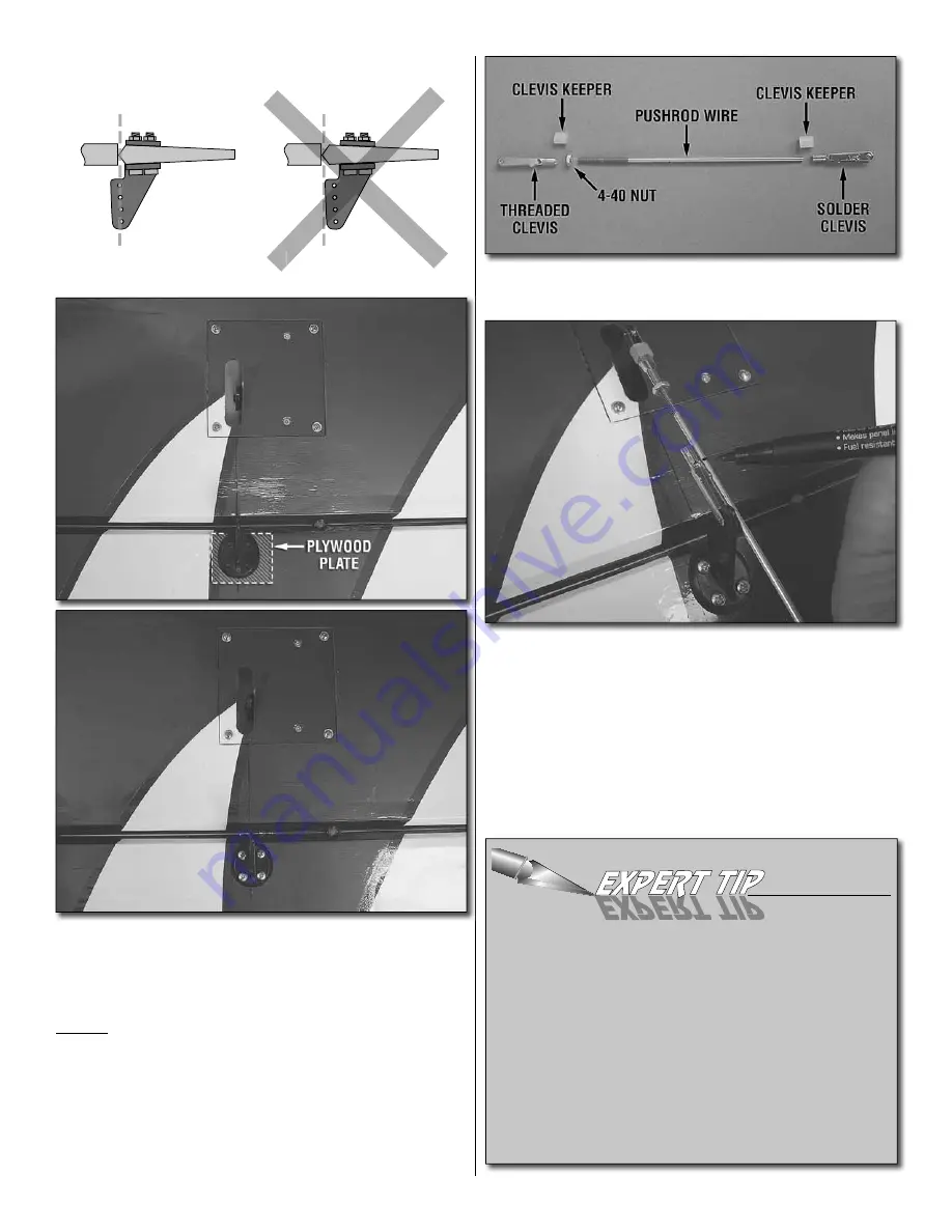
9. Install the clevis to the servo arm and install
the solder clevis to the aileron control horn. Center the aileron
and the aileron servo arm. Make a mark on the wire that aligns
with the front of the round portion of the clevis. Remove the
pushrod assembly from the servo. Cut the wire on the mark
and then solder the 4-40 solder clevis to the un-threaded
end of the pushrod wire. The following “Soldering Tip” may be
helpful if you are not familiar with soldering techniques.
HOW TO SOLDER
1. Use denatured alcohol or other solvent to thoroughly
clean the pushrod. Roughen the end of the pushrod with
coarse sandpaper where it is to be soldered.
2. Apply a few drops of soldering fl ux to the end of the
pushrod, and then use a soldering iron or a torch to heat
it. “Tin” the heated area with silver solder by applying the
solder to the end. The heat of the pushrod should melt the
solder – not the fl ame of the torch or soldering iron – thus
allowing the solder to fl ow. The end of the wire should be
coated with solder all the way around.

