9
3. Place the clevis on the end of the pushrod. Add another
drop of fl ux, and then heat and add solder. The same as
before, the heat of the parts being soldered should melt
the solder, thus allowing it to fl ow. Allow the joint to cool
naturally without disturbing. Avoid excess blobs, but make
certain the joint is thoroughly soldered. The solder should
be shiny, not rough. If necessary, reheat the joint and allow
to cool.
4. Immediately after the solder has solidifi ed, but while it
is still hot, use a cloth to quickly wipe off the fl ux before
it hardens.
Important:
After the joint cools, coat the joint
with oil to prevent rust.
Note:
Do not use the acid fl ux that
comes with silver solder for electrical soldering.
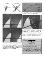
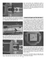
This is what a properly soldered clevis looks like – shiny
solder with good flow, no blobs and flux removed.
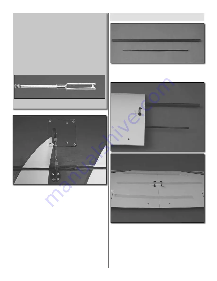
10. Once the solder has cooled, install the pushrod to the
servo arm and the second hole from the end of the aileron
control arm. Be sure to slide the clevis keepers over the clevis
and tighten the 4-40 nut.
❏
11. Repeat steps 1-10 for the lower left wing panel, the
top right wing panel and the top left wing panel.
Note:
When
the servo leads get pulled through the top wings the leads
will exit out the holes in the bottom of the wing.
Join the Bottom Wing Panels
❏
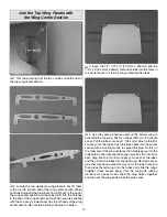
1. Locate the 1/4" x 12-1/4" [6.4mm x 311mm] and the
1/2" x 17-3/4" [12.7mm x 450mm] composite tubes. Test fi t
them into the holes in the root rib.
❏
2. Mix 1/2 ounce [15 mL] of 30 minute epoxy. Apply epoxy
into the tube holes in the right and left wings as well as the
root rib of each wing. Brush a thin fi lm of epoxy onto each
of the tubes and then insert the tubes into the right wing.
Remove excess glue that may have worked its way out of the
tube holes and then place the left wing onto the tubes and
slide the wings together. Clean excess epoxy from the wing
with rubbing alcohol and a paper towel. Tape the wing halves
together and then set the wing aside while the glue cures.

