9
❏
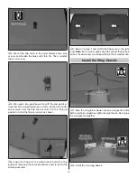
4. Install the aileron and fl aps – with fi nal gap less than
1/16" [1.5 mm].
❏
5. Move the ailerons and fl aps a few times to align the
hinges. Allow the epoxy to fully cure.
❏
6. Return to Step 1 and install the hinges in the other
wing panel.
Install the Aileron Servo
Begin with the left wing panel.
We will show the installation of the S.Bus Set-up using
non-S.Bus digital servos.
❏
❏
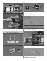
1. Install a servo lead extension (not included). Secure
the connection with tape or shrink tubing (not included).
❏
❏
2. Install rubber grom-
mets and metal eyelets on
both aileron and fl ap servos.
❏
❏
3.
S.Bus Only:
If using a non-S.Bus servo, the
Decoder
will need to be programmed. If using an S.Bus servo the
servo
will need to be programmed. With S.Bus any servo can be
programmed to any channel. The left aileron servo in this wing
is going to be set to channel 1. Follow the manual included
with your transmitter if it has a port for programming S.Bus
servos. If not, follow the instructions included with the Futaba
Channel Changer to set the S.Bus servo or the connector on
the Futaba Decoder to channel 1. While programming the
Decoder, set a second connector on the decoder to channel
6 for the left fl ap. Place a number decal on both connectors.
❏
❏
4.
S.Bus Only:
Connect the non-S.bus aileron servo
to channel 1 on the Decoder. Or, connect the S.Bus servo
to a 300mm S.Bus Hub.


