12
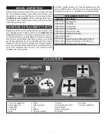
HOW TO SOLDER
Apply a few drops of soldering fl ux to the end of the
pushrod. “Tin” the end of the pushrod by applying heat.
Apply silver solder to the heated area. The pushrod should
melt the solder, not the soldering iron. The end of the
pushrod should be tinned all the way around.
Position the solder clevis on the pushrod and apply a drop
of fl ux to the joint. Apply heat and add solder. Again, the
heat of the part should melt the solder, not the soldering
iron. Allow the part to cool naturally. Make sure the joint is
thoroughly soldered. It should be shiny, not rough. Reheat
if necessary.
Wipe off the fl ux residue with denatured alcohol. Coat the
joint with oil to prevent rust.
❏
❏
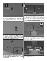
21. Install the nut and retainers.
❏
❏
22. Reinstall the aileron pushrod and slide the retainers
over the clevises.
❏
23. Repeat steps 1 – 22 to install the aileron servo in the
right wing. The two aileron servos can be connected with a
Y-harness and plugged into the aileron channel on the receiver.
Each aileron can be plugged into a separate channel or as
shown, set-up with S.Bus. We set up the aileron in the
right
wing
half
on channel 5 and the fl ap on channel 7.
Install the Flap Servo
❏
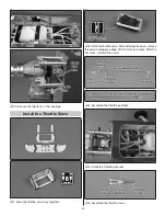
1. Install a servo lead extension (not included). Secure the
connection with tape or shrink tubing (not included).
❏
2. Trim the covering from over the fl ap servo opening in
the left wing panel.
❏
3. Route the flap servo lead out the wing root. Or
connect the flap servo to the S.Bus Hub or channel 6 on
the S.Bus Decoder.


