background image

GRAUPNER/SJ GmbH   D-73230 KIRCHHEIM/TECK   GERMANY 

Modifications reserved. No liability for printing errors.  


       02/2014 

3


Essential tools and adhesives (not included) 
Cyano-acrylate glue (“cyano”) 


Order No.5821 

Cyano-acrylate activator   


Order No.953.150 

You will also need the following: abrasive paper, 1.5 mm A/F allen key, screwdriver. 
 
Assembling the model 
The airframe requires just a few glued joints and assembly steps to complete, but the 
following  instructions  must  still  be  observed  carefully  to  ensure  that  the  model  flies 
safely. 
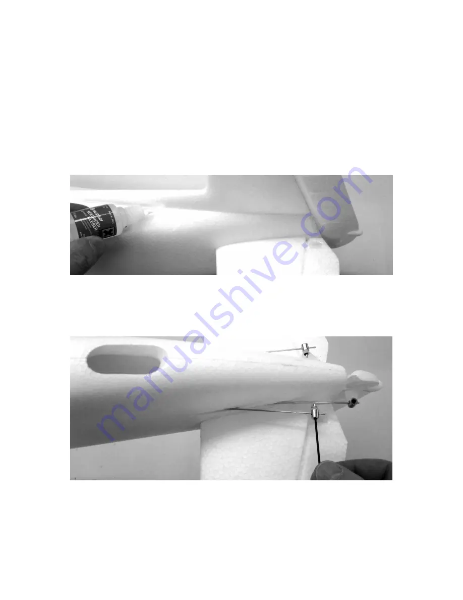
The first step is to open the canopy: grasp it firmly at the rear end, and pull it upwards 
and off. Now use a servo tester or your radio control system to centre the rudder and 
elevator servos. 


The  photo  shows  the  fuselage  with  the  tailplane  and  fin  inserted.  Push  the  panels 
into their slots as far as they will go, set them exactly “square”, and slip the pushrods 
through  the  swivel  connectors.  When  you  are  satisfied,  apply  low-viscosity  cyano-
acrylate  (“thin  cyano”)  along  the  joints.  Caution:  do  not  use  activator  for  these 
joints, as this will prevent the adhesive running fully into the joints.


Allow the glue to set hard, then tighten the grubscrews in the swivel connectors using 
the 1.5 mm A/F allen key. Ensure that both elevator panels are exactly parallel and at 
neutral (centre).  
Caution: after tightening the grubscrews check that the pushrods are securely 
fixed. If either of them should work loose, the model is likely to crash. 

Содержание HoTT Deluxe 9932.100

Страница 1: ...HEIM TECK GERMANY Modifications reserved No liability for printing errors 02 2014 1 No 9932 100 ASSEMBLY INSTRUCTIONS HoTT DELUXE ARTF RC model aircraft fitted with brushless power system This model r...

Страница 2: ...n the fin Please take the time to read right through these operating instructions before attempting to operate the model Pack contents 1 Ready made fuselage fitted with control surface linkages and de...

Страница 3: ...w use a servo tester or your radio control system to centre the rudder and elevator servos The photo shows the fuselage with the tailplane and fin inserted Push the panels into their slots as far as t...

Страница 4: ...This completes work on the fuselage The next step is to glue the four plywood parts in place as shown It is essen tial to sand the joint surface of all four rectangles to obtain really strong glued jo...

Страница 5: ...te the servo leads through the bottom opening in the fuselage Please bear in mind that connecting the G 3 5 plug and socket as shown in the photo switches the receiver on In this state the motor could...

Страница 6: ...wn in the drawing Note that the decals must be slit along the control surface hinge lines otherwise the control surfaces will jam The windscreen is supplied in three parts so that it can be applied to...

Страница 7: ...pare the model fully It should be given a fairly brisk hand launch directly into the wind trotting forward for a few paces gives the right launch speed The model s nose should be inclined up by about...

Страница 8: ...pment in other ways Dry cells and rechargeable batteries must be removed from the device and taken separately to a suitable battery disposal centre If you don t know the location of your nearest dispo...

Страница 9: ...d ensure that all the control surfaces work smoothly and deflect in the correct sense in relation to the stick movements If you are a beginner to this type of model flying we recommend that you enlist...

Страница 10: ...tary claims especially for reimbursement of costs relating to the defect e g installation removal costs and compensation for consequent damages unless they are allowed by statute This does not affect...

Отзывы: