GRAUPNER GmbH & Co. KG D-73230 KIRCHHEIM/TECK GERMANY
Modifications reserved. No liability for printing errors
12/2010
0062196
10
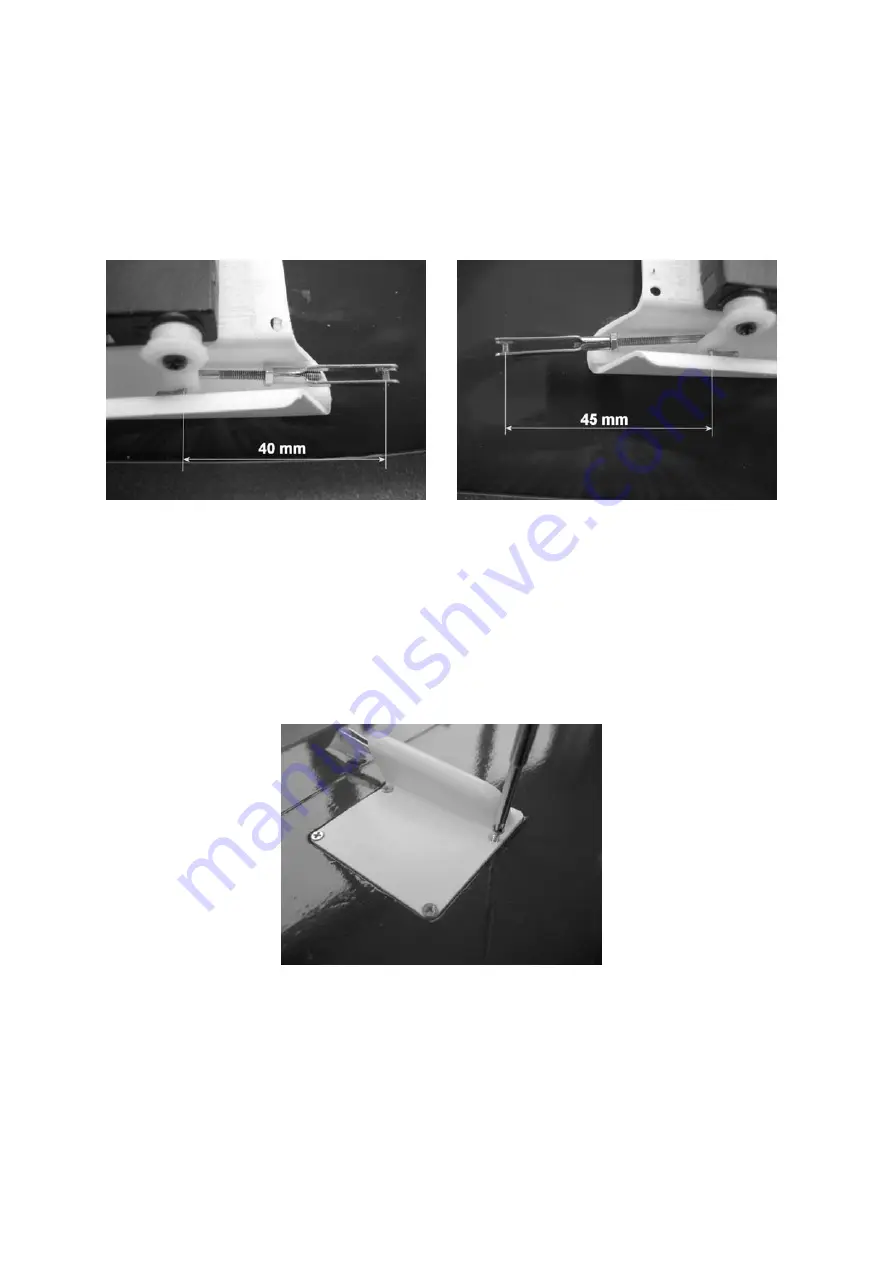
Each aileron and flap pushrod is assembled using an M2 threaded rod, an M2 nut
and an M2 clevis, as supplied in the kit. Note that the angled end of the aileron push-
rods must be formed in such a way that the distance between the linkage hole on the
servo output arm and the clevis linkage pin is 40 mm. For the flaps the same dimen-
sion is 45 mm. Final adjustment can be made later by screwing the clevis in or out on
the threaded rod, once you have screwed the servo cover in place.
It is essential to apply a drop of UHU schraubensicher (thread-lock fluid) between the
clevis and the locknut to prevent the clevis working loose.
You can now connect the clevises to the control surface horns, and fix the servo well
covers in place using the countersunk screws supplied; drill pilot-holes for the screws
beforehand. TIP: if you want the last word in aerodynamic efficiency you can
countersink the screw-holes in the moulding.
There are two possible methods of connecting the servos to the receiver: one is to
route the servo extension leads from the receiver out of the openings in the fuselage,
and then connect them to the extension leads in the wings when the model is rigged;
the other is to solder the extension leads to the wing servo quick-connectors, Order


