

FC7000-UM-251-9370
7-20
7. ADJUSTMENT
7.3.9 Adjusting the Auto-Registration Mark Sensor Sensitivity
If you replace the main board, you need to adjust the sensitivity.
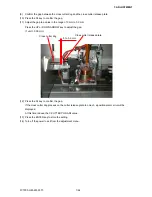
How to adjust the auto-registration mark sensor sensitivity
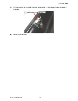
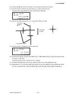
(1) Load an A4 (Letter) or larger size sheet of paper in the plotter. The paper color must be white, and it is
recommended that high-quality paper made for ink-jet printers be used.
(2) Enter the adjustment menu (see Section 7.3.6).
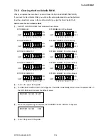
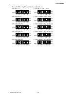
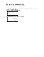
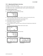
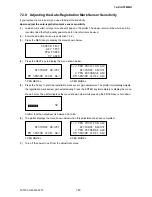
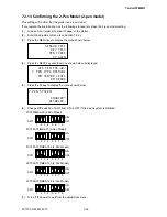
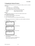
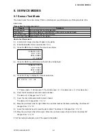
(3) Press the MENU key to display the menu shown below.
SENSOR TEST
KEY TEST
PEN FORCE
XY GAIN
(4) Press the NEXT key to display the menu shown below.
DISTANCE ADJUST
RM SENSOR LEVEL ADJ
1/2 PEN POSITION ADJ
DISTANCE ADJUST
2 PEN EXCHANGE ADJ
RM SENSOR LEVEL ADJ
1-PEN MODEL
2-PEN MODEL
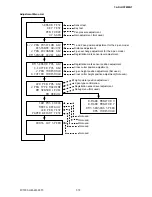
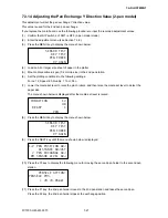
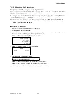
(5) Press the F4 key to start the registration mark sensor gain adjustment. The plotter immediately adjusts
the registration mark sensor gain automatically. Press the ENTER key immediately to display the menu
shown below. The plotter displays the menu shown below while pressing the ENTER key is hold down.
50
Confirm that the output level is between 50 to 60.
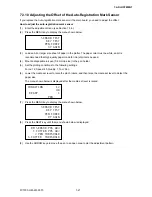
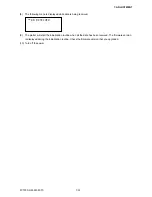
(6) The plotter displays the menu shown below when this adjustment has been completed.
DISTANCE ADJUST
RM SENSOR LEVEL ADJ
1/2 PEN POSITION ADJ
DISTANCE ADJUST
2 PEN EXCHANGE ADJ
RM SENSOR LEVEL ADJ
1-PEN MODEL
2-PEN MODEL
(7) Turn off the power to exit from the adjustment menu.
Содержание FC7000-100
Страница 1: ...CUTTING PLOTTER SERVICE MANUAL FC7000 75 100 130 160 FC7000MK2 60 75 100 130 160 FC7000 UM 251 10 9370...
Страница 2: ......
Страница 8: ......
Страница 34: ......
Страница 38: ......
Страница 100: ......
Страница 110: ......
Страница 112: ...FC7000 UM 251 9370 10 2 10 PARTS LIST 1 2 3 4 5 6 7 8 10 9 Control Panel Assy 11 12...
Страница 114: ...FC7000 UM 251 9370 10 4 10 PARTS LIST Control Panel 5 4 3 6 9 8 7 1 1 2 3 5 10...
Страница 126: ......
Страница 141: ...FC7000 UM 251 9370 11 15 11 BLOCK DIAGRAMS AND CIRCUIT DIAGRAMS 11 3 2 Main Board CPU...
Страница 142: ...FC7000 UM 251 9370 11 16 11 BLOCK DIAGRAMS AND CIRCUIT DIAGRAMS 11 3 3 Main Board FPGA...
Страница 143: ...FC7000 UM 251 9370 11 17 11 BLOCK DIAGRAMS AND CIRCUIT DIAGRAMS 11 3 4 Main Board I F...
Страница 144: ...FC7000 UM 251 9370 11 18 11 BLOCK DIAGRAMS AND CIRCUIT DIAGRAMS 11 3 5 Main Board Motor Drive...
Страница 145: ...FC7000 UM 251 9370 11 19 11 BLOCK DIAGRAMS AND CIRCUIT DIAGRAMS 11 3 6 Main Board Memory...
Страница 146: ...FC7000 UM 251 9370 11 20 11 BLOCK DIAGRAMS AND CIRCUIT DIAGRAMS 11 3 7 Main Board Power Supply...


